
Related Manuals for Applied Motion Products 1240i


Summary of Contents for Applied Motion Products 1240i
- Page 1 Hardware Manual 1240i Programmable Step Motor Driver motors • drives • controls SHOP ONLINE at www.airlinehyd.com 800-999-7378...
-
Page 2: Table Of Contents
Table of Contents Introduction Thank you for selecting an Applied Motion Products motor control. We hope our Introduction -----------------------------------------------------------------------4 dedication to performance, quality and economy will make your motion control project successful. If there’s anything we can do to improve our products or help you Features ---------------------------------------------------------------------------4 use them better, please call or fax. -
Page 3: Getting Started
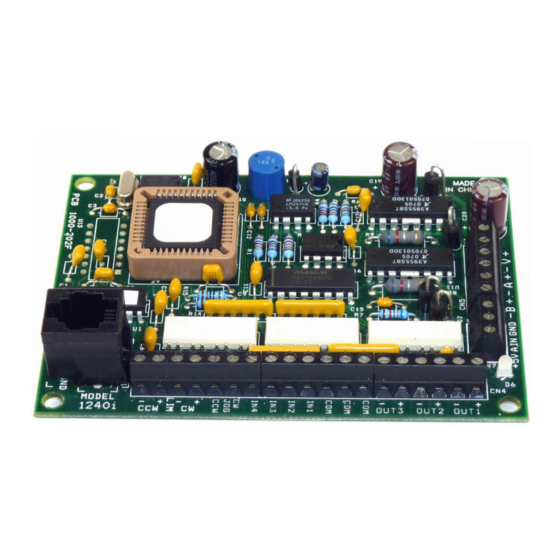
The sketch below shows where to find the important connection and adjustment points. Please examine it now. DC Power 1240i Supply There are two versions of the 1240i, one has an added 3-pin connector CN7. 12 - 42 V 1A fuse All Mating connectors included. mounting hole (1 of 4) -
Page 4: Choosing A Power Supply
Voltage Insulate unused motor leads separately, and then secure. Chopper drives like the 1240i work by switching the voltage to the motor terminals Never connect motor leads to ground or to a power supply. on and off while monitoring current to achieve a precise level of phase current. To do this efficiently and silently, you’ll want to have a power supply with a voltage... -
Page 5: Connecting To The Pc -------------------------------------------------------------9 Jogging
5 to 24 volts DC. This also allows you to have long wires on limit sensors that may be far from the 1240i with less risk of intoducing noise to the 1240i. The schematic diagram of the limit switch input circuit is shown below. -
Page 6: Wiring A Mechanical Limit Switch
If your sensor has an open collector output or a sinking output, wire it like this: 3540i, Si3540, Si5580, 7080i and Si4500 indexer-drives. CW LIMIT+ 1240i Note: If current is flowing into or out of an 1240i input, the logic state of that input is output CW LIMIT- Limit Power low. -
Page 7: Wiring Outputs
Connecting an Input to the Si-1 Motion Output (Set Si-1 motion signal to “in position”. Si-1 will trigger 1240i at end of each move). Note: At power-up, the 1240i sets all three programmable outputs high (open cir- cuit). -
Page 8: Microstepping
Half stepping divides each The 1240i has four 0.156 inch diameter holes in the circuit board for mounting. step into two smaller steps by alternating between both phases on and one phase on. -
Page 9: Mounting The Optional Mmi
The first is a fairly thin section that contains the keypad, display and some you choose, you’ll need to connect the MMI to your 1240i with the MMI cable. The circuit boards. The other part is thicker and contains the telephone jack and a cable MMI has the same telephone style connector as the 1240i. -
Page 10: Recommended Motors
Recommended Motors Mechanical Outline 4.00 IN. 3.85 IN. Motor Winding Max Torque Current Setting Number Connection oz-in Amps/phase 0.15 IN. HT11-012 series HT11-013 series 5014-842 series 0.15 IN. HT17-068 parallel parallel HT17-072 2.85 IN. parallel HT17-076 HT23-393/593 parallel 3.00 IN. parallel HT23-396/596 HT23-399/599... -
Page 11: Technical Specifications
Technical Specifications Mechanical Outline - Optional MMI Amplifiers Dual H-bridge, 3 state, pulse width modulated (PWM) switching at 25 2.988 kHz. 0.1 - 1.2 amps/phase output current, software selectable. 48 watts maximum output power. Automatic idle current reduction (software 0.960 programmable) reduces current to motor when idle. - Page 12 Notes Applied Motion Products, Inc. 404 Westridge Drive Watsonville, CA 95076 Tel (831) 761-6555 (800) 525-1609 Fax (831)-761-6544 http://www.applied-motion.com Copyright 2000 -23- SHOP ONLINE at www.airlinehyd.com 800-999-7378...
Need help?
Do you have a question about the 1240i and is the answer not in the manual?
Questions and answers