
Related Manuals for Applied Motion Products 3540i


Summary of Contents for Applied Motion Products 3540i
- Page 1 7/31/98 Hardware Manual 3540i Programmable Step Motor Driver Copyright 1998 Applied Motion Products, Inc. 404 Westridge Drive Watsonville, CA 95076 Tel (831) 761-6555 (800) 525-1609 Fax (831) 761-6544...
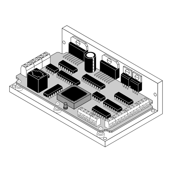
- Page 2 Mechanical Outline - Optional MMI -19-...
-
Page 3: Technical Specifications
Introduction Technical Specifications Thank you for selecting an Applied Motion Products motor control. We hope our dedication to performance, quality and economy will make your motion control Amplifiers Dual, MOSFET H-bridge, 3 state, pulse width modulated project successful. If there's anything we can do to improve our products or help switching at 20 kHz. -
Page 4: Getting Started
Getting Started Recommended Motors Motor Size Winding Max Torque Current To use your 3540i motor control, you will need the following: Number inches Connection oz-in Amps 5014-842 1.38 x 1.38 x 1.57 4 lead a power supply (see page 5 for help in choosing one). -
Page 5: Connecting The Power Supply
Voltage diameter for the connector to fit Chopper drives like the 3540i work by switching the voltage to the motor terminals through. You will also need two holes on and off while monitoring current to achieve a precise level of phase current. To that line up with the big mounting do this efficiently and silently, you’ll want to have a power supply with a voltage... -
Page 6: Mounting The Drive
MMI. If this is the case, and you need to reprogram the 3540i, you can use any telephone line cord as a programming cable. They are available at most supermarkets and discount stores. -
Page 7: Connecting The Motor
Never disconnect the motor while the power is on. Never connect motor leads to ground or to a power supply. Microstepping drives like the 3540i precisely control the amount of current in each phase at each step position as a means of electronically subdividing the steps even further. -
Page 8: Wiring Outputs
Since there is no electrical connection to the 3540i, you must provide the source of • Your 3540i was shipped with a black adapter plug. It has a telephone style jack current and voltage, typically from a power supply. You must also limit the current at one end and a larger 9 pin connector at the other . -
Page 9: Limit Switches
Connecting an Input to the SI-1 Motion Output power supply - terminal. Then connect the COM and power supply + terminals. (Set SI-1 motion signal to "in position". SI-1 will trigger 3540i at end of each move.) inside 3540i 5-24... - Page 10 Si5580, 7080i and MC8400 indexer-drives. CW LIMIT+ Note: if current is flowing into or out of an 3540i input, the logic state of that input 3540i output is low. If no current is flowing, or the input is not connected, the logic state is high.
Need help?
Do you have a question about the 3540i and is the answer not in the manual?
Questions and answers