Table of Contents
Advertisement
Quick Links
Advertisement
Table of Contents

Subscribe to Our Youtube Channel
Related Manuals for Atmos i View PRO Series


Summary of Contents for Atmos i View PRO Series
- Page 1 English ATMOS i View PRO GA1GB.120102.0 2022-04 Index: 19...
-
Page 2: Table Of Contents
Endoscope adapter ..........21 3.2.5 Rear view of the control device of the 4.19 HD adapter............21 ATMOS i View 31 PRO (not with an integrated HD camera) ...............11 Cleaning and care ..........22 3.2.6 Rear view of the control device of the... -
Page 3: Introduction
Care and safety inspections in conjunction with professional execution provide for operational safety and readiness for use of your ATMOS i View PRO and are therefore a must besides regular cleaning. Repair work and safety inspections may be carried out only by expert personnel authorized by ATMOS. -
Page 4: Intended Purpose
1.0 Introduction 1.2 Intended purpose Product name: ATMOS i View 21 PRO ATMOS i View 31 PRO Main functions: The device is a microscope intended to give a magnified illuminated spacial view on human tissue for diagnostic and treatment purposes. -
Page 5: Function
LED light source on and off despite the activated automatic light control. Due to the variety of options the ATMOS i View PRO has to offer, the user is in a position to configure a microscope to suit his requirements. -
Page 6: Explanation Of Pictures And Symbols
● Numeration Engage, check correct fi t click Warning, pay special attention Important information Symbols ATMOS i View PRO Serial number Reference number Date of manufacture Manufacturer Consult operating instructions Follow operating instructions (blue) Weight adjustment for the carrier arm... -
Page 7: Scope Of Supply
Sensor Record Freeze PC/USB Prior to dispatch, the ATMOS i View PRO was subjected to an extensive functional test and was carefully packed. Nevertheless, Microscope please compare the contents of the shipment on completeness immediately upon receipt (see delivery note). -
Page 8: For Your Safety
• The ATMOS i View PRO complies with the electromag- • The ATMOS i View PRO is a device designed in line with netic immunity requirements of standard IEC 60601-1-2 IEC 60601-1 / EN 60601-1 and is a protection class I / EN 60601-1-2 “Electromagnetic Compatibility –... -
Page 9: Setting Up And Starting Up
3.0 Setting up and starting up 3.1 Overview ATMOS i View 21 PRO ATMOS i View 31 PRO Examination microscope with an integrated, Examination microscope with an integrated, Description fanless, high-transmission, high-performance fanless, high-transmission, high-performance LED light in the microscope head... -
Page 10: Setting Up
Please note that only PCs and monitors with IEC 60601-1 / EN 60601-1 approval may be connected to the video outlets of the ATMOS i View PRO supply module! Please note that only the ATMOS Strobo 21 LED may be connected to the strobe port of the ATMOS i View PRO supply module! 3.2.1 Connection to the power supply Potential equalization: The ATMOS i View’s supply module has a rear connection for potential equalization which can be connected to the potential equali-... -
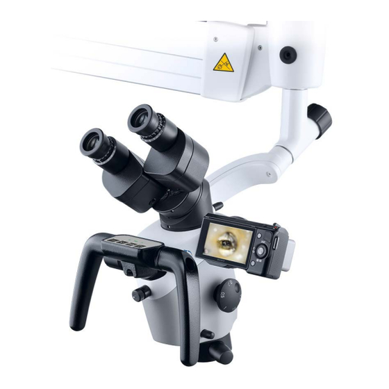
Page 11: Operating Elements On The Microscope
Datum Benennung (designation) Tasterfolie Erstellt 27.03.3013 C.Reinhardt 3.2.5 Rear view of the control device of the ATMOS i View 31 PRO (not with an integrated HD camera) Bearb. Gepr. Output signal of IEC power plug with fuse inlay Output signals of... -
Page 12: Rear View Of The Control Device Of The Atmos I View 31 Pro With An Integrated Hd Camera
The ceiling mount is suitable for accommodating the ATMOS i View PRO and a monitor weighing up to 10.5 kg. Only the supply module of the ATMOS i View PRO and the monitor may be connected to the power supply outlets of the ceiling mount. -
Page 13: Starting Up
• Take into consideration when setting up the microscope that the elastic force of the arm – without microscope head – is exceed- ingly strong. Operate the brake of the height adjustment carefully. • To activate the ATMOS i View PRO, please press the on/off switch on the front side of the control device. 3.5 Operating requirements Please note that the following requirements must be adhered to for further operation after installing the device: •... -
Page 14: Starting Up At A Glance
3.0 Setting up and starting up 3.6 Starting up at a glance Adjust microscope to initial position on the microscope suspension by using the fixing wheel. Adjust microscope horizontally and vertically. Adjust all clamps on the carrier and float arm to suit the movability of the arm to the requirements. Swing in microscope into the working space. -
Page 15: Operation
Automatic light switching: Once the arm is in the upper position, the LED light of the microscope switches off auto- matically. 4.3 Hand grips When purchasing the ATMOS i View PRO, you may choose between two versions of handles. 4.3.1 T-hand grip (see fi gure) 4.3.2 Lateral double hand grip... -
Page 16: Adjusting The Interocular Distance
4.0 Operation 4.4 Adjusting the interocular distance The interocular distance is adjustable between 50 and 75 mm. • Swivel the microscope into the working space. • Look through the eyepieces and push or pull the lens tube together or apart with both hands. The interocular distance is perfectly adjusted when you look through with both eyes and see single circular pic- ture. -
Page 17: Exchanging The Lenses
Tighten the three grub screws. 4.9 Adjusting the 5-fold magnification changer The 5-fold magnification changer from ATMOS enables free range zoom from 0.5x up to 2.0x. • Select the desired zoom factor by selecting one of the lateral rotary knobs. -
Page 18: Focusing
4.0 Operation 4.10 Focusing • Adjust the zoom to maximum (2.0) on the magnifi cation unit. • Approach the object with the microscope until the image is sharp. • If the zoom level is changed, the pre-adjusted degree of sharpness is still maintained. 4.10.1 Fine focusing The optional fi ne focusing allows for sensitive and precise focusing in a 17 mm range. -
Page 19: Shadowless Illumination
4.0 Operation 4.14 Shadowless illumination The option shadowless illumination prevents instruments from causing shadows in the field of view. This option cannot be retrofit- ted. • For shadowless illumination, no operating steps are required. 4.15 Microscope zoom and object field size Lens f in mm Factor display on the magnification unit Eyepieces with... -
Page 20: Image And Video Recording
4.17 Image and video recording Integrated camera: If desired, an HD camera can be inte- grated in the ATMOS i View 31 PRO. External video recorder: External video recorders can be controlled via the control panel buttons if they are connected to the jack plugs “Freeze”... -
Page 21: Endoscope Adapter
Due to the specially developed HD adapter, it is possible to connect a SONY digital camera with e-mount bayonet to the ATMOS i View PRO. This camera enables you to take and archive HD resolution pictures. At dispatch, the HD adapter is covered with a cover cap. -
Page 22: Cleaning And Care
Residues can be removed with a mixture made from equal parts of ethyl alcohol and distilled water to which a drop of standard washing-up liquid is added. If fl uids have penetrated the ATMOS i View PRO, it must be sent in and may only be used after being checked by a person authorized by ATMOS. -
Page 23: Fogging Of Optical Surfaces
To prevent the eyepiece optics from fogging, we recommend using an anti-fogging agent. Note: Anti-fogging agents used by opticians for eyeglass lenses are also suitable for the ATMOS i View PRO’s optics. • Please observe the instructions supplied with each anti-fogging agent. -
Page 24: Maintenance And Service
• Place any used accessories with the product. • ATMOS recommends: Work should be carried out by an • Fill in form QD 434 “Delivery complaint / return shipment” authorized ATMOS service partner. This ensures that repairs and the respective decontamination certifi cate. -
Page 25: Troubleshooting
Contact ATMOS Service The ATMOS i View PRO was moved into “parking position” and thereby the light Pull the ATMOS i View PRO into working position was switched off Too little or no light at all Malfunction of the LED light source... -
Page 26: Accessories And Options
Binocular rotary disk with detent 538.3300.0 Cable (only for the ATMOS i View 31) Cable HDMI type A/C, L = 5 m (only with an integrated HD camera) 538.1902.0 Cable HDMI extension, L = 5 m (only with an integrated HD 008.0909.0... -
Page 27: Technical Data
CE mark Ident-Nr. (REF) 538.0000.0 ATMOS i View 21 539.0000.0 ATMOS i View 31 538.9000.0 ATMOS i View 21 PRO 539.9000.0 ATMOS i View 31 PRO 605.0000.0 ATMOS i View 21 COLPO 606.0000.0 ATMOS i View 31 COLPO Status of the Technical Data: 11.11.2020... -
Page 28: Disposal
Appliances Register), this type of device is excluded from ElektroG regulations. In order to guarantee proper disposal of your old device, please either pass on your old device to your specialized dealer or send it directly to ATMOS MedizinTechnik for profession- al disposal. -
Page 29: Notes On Emc
HF-shielded room of a magnetic resonance imaging system. The customer or user of the ATMOS i View 21 / 31 PRO must ensure that the device is used in a prescribed environment. Guidance and manufacturer’s declaration – key features ) Please note the Technical Data in these instructions. -
Page 30: Notes
12.0 Notes... - Page 31 12.0 Notes...
- Page 32 ATMOS MedizinTechnik GmbH & Co. KG Ludwig-Kegel-Str. 16 79853 Lenzkirch / Germany Phone: +49 7653 689-0 info@atmosmed.com www.atmosmed.com...
Need help?
Do you have a question about the i View PRO Series and is the answer not in the manual?
Questions and answers