Sanyo DVD-SL40 (XE) Service Manual
Hide thumbs
Also See for DVD-SL40 (XE):
- Service manual (24 pages) ,
- Service manual (14 pages) ,
- Instruction manual (21 pages)
Table of Contents
Advertisement
Quick Links
Service Manual
/ON
AUDIO
SUBTITLE
OPEN/CLOSE
RANDOM
ZOOM
ANGLE
REPEAT
A-B REPEAT
ENT
RETURN
TOP MENU
MENU
SETUP
ON SCREEN
SLOW
SEARCH MODE
PAUSE/STEP
PREV
NEXT
PLAY
REV
FWD
PROGRAM
1
2
3
4
5
6
0
7
8
9
+10
REMOTE CONTROLLER RB-SL40
(Caution)
There are two kinds of this model.
Type A : The DVD mechanism of part code "645 066 3802" is used for this type.
The 10th figure of a serial number is nothing or "A".
Type B : The DVD mechanism of part code "645 068 7495" is used for this type.
The 10th figure of a serial number is "B" or "C".
The differences between Type A and Type B are a DVD driver and a main p.w.board.
CONTENTS
DVD Mechanism Replacement ............................................. 1
Laser beam safety precaution ............................................... 1
Mechanism replacement ....................................................... 2
How to load software for main p.w.board .............................. 3
Sevice mode ......................................................................... 4
Exploded View (Cabinet & Chassis) ..................................... 5
Parts List ............................................................................... 6
Exploded View (DVD Mechan ism) ....................................... 8
Parts List ............................................................................... 8
IC Block Diagram & Description ............................................ 10
Block Diagram ...................................................................... 14
wiring Connection ................................................................. 15
Schematic Diagram ............................................................... 16
Wiring Diagram .................................................................... 28
All manuals and user guides at all-guides.com
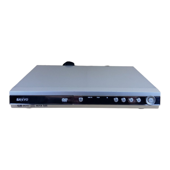
DVD Video Player
FILE NO.
DVD-SL40
(XE)
PRODUCT CODE No.
137 123 05
SM
REFERENCE No.
5810569
Advertisement
Table of Contents

Related Manuals for Sanyo DVD-SL40 (XE)


Summary of Contents for Sanyo DVD-SL40 (XE)
-
Page 1: Table Of Contents
All manuals and user guides at all-guides.com FILE NO. DVD-SL40 DVD Video Player Service Manual (XE) AUDIO SUBTITLE OPEN/CLOSE RANDOM ZOOM ANGLE REPEAT A-B REPEAT RETURN TOP MENU MENU SETUP ON SCREEN SLOW SEARCH MODE PAUSE/STEP PREV NEXT PLAY PROGRAM REMOTE CONTROLLER RB-SL40 (Caution) There are two kinds of this model. -
Page 2: Dvd Mechanism Replacement
All manuals and user guides at all-guides.com DVD MECHANISM REPLACEMENT 1. Cautionary instructions in handling the assy Do not connect or disconnect roughly by an excessively strong (Safety instructions) force, or a broken wire or bad contact may result. Optical pickup Semiconductors are connected. -
Page 3: Mechanism Replacement
All manuals and user guides at all-guides.com MECHANISM REPLACEMENT 1. How to Remove DVD Mechanism Side of DVD mechanism First, it is necessary to remove Escutcheon. Front Rear Cylindrical thing How to remove Escutcheon. An eject button is pushed and a tray is taken out. Please remove Escutcheon, as shown in the left figure 2 . -
Page 4: How To Load Software For Main P.w.board
All manuals and user guides at all-guides.com MECHANISM REPLACEMENT 4. Tray parts. 5. Base mechanism mounting parts. G-SANKOL G-SANKOL G-SANKOL (Type A) G-SANKOL : Clean the groove by alcohol well. (Type B) HOW TO LOAD SOFTWARE FOR MAIN P.W.BOARD 1. Power on, then open tray. 2. - Page 5 All manuals and user guides at all-guides.com SERVICE MODE A. Market / Region SETUP In the initial condition for this model, Market and Region information are undefined. MARKET MARKET MARKET In the following cases, be sure to set up Market/Region. 1.
-
Page 6: Exploded View (Cabinet & Chassis)
All manuals and user guides at all-guides.com EXPLODED VIEW (CABINET & CHASSIS) - 5 -... -
Page 7: Parts List
D0102 645 067 9278 ZENER DIODE 5.6V,MMSZ52532B 645 067 9605 DOOR LENS D0507 645 064 0056 DIODE CHIP 1N4148W,BAV16W 645 064 0674 LOGO,SANYO DD016 645 064 0056 DIODE CHIP 1N4148W,BAV16W 645 068 7457 DVD DOOR FB001 645 067 9223 INDUCTOR 1UH 10%... -
Page 8: Parts List
All manuals and user guides at all-guides.com PARTS LIST REF.NO. PART NO. DESCRIPTION POWER P.W.BOARD ASSY REF.NO. PART NO. DESCRIPTION 645 068 8393 ASSY IC MBM29LV160TE, 614 331 0310 ASSY,PWB,POWER(Only initial) IC+SOFTWARE C0101 645 064 0988 CONDUCTOR SAFETY (IC MBM29LV160TE-70TN)(N.S.P) C0107 645 064 0995 CONDUCTOR SAFETY 645 068 8416 ASSY IC M29LV1600T-7,... - Page 9 All manuals and user guides at all-guides.com EXPLODED VIEW (DVD MECHANISM(Type A)) DM15 DM15 DM01 DM15 DM16 DM16 DM02 DM16 DM17 DM05 DM03 DM06 DM17 DM04 DM07 DM23 DM08 DM17 DM09 DM10 DM22 DM12 DM11 DM13 DM14 PARTS LIST MECHA SW P.W.BOARD ASSY DVD DECK MECHANISM CHASSIS (Type A) REF.NO.
- Page 10 All manuals and user guides at all-guides.com EXPLODED VIEW (DVD MECHANISM(Type B)) DM15 DM01 DM16 DM02 DM18 DM15 DM05 DM15 DM16 DM03 DM16 DM06 DM04 DM19 DM07 DM08 DM18 DM21 DM19 DM09 DM10 DM20 DM12 DM11 DM13 DM14 PARTS LIST REF.NO.
-
Page 11: Ic Block Diagram & Description
All manuals and user guides at all-guides.com IC BLOCK DIAGRAM & DESCRIPTION IC001 IMP809SEUR-T (Reset) IC004 RC4558 (Ope. Amp.) 1OUT 1IN- 2OUT IMP809 (IMP810) 1IN+ 2IN- 2IN+ (RESET) RESET IC005,IC114,115 B1117N-2.85 (Regulator) SOT - 223 SOT - 223 Tab V Tab V Adj/GND Adj/GND... - Page 12 All manuals and user guides at all-guides.com IC BLOCK DIAGRAM & DESCRIPTION IC102 SFH615A-3 (Opt. Sensor) IC201 TL431 (Regulator) (Top view) Cathode Anode Reference Anode Collector Cathode Emitter IC103 MBM29LV800BA ( Flash) IC104 AT24C02N-10SI-2.7 (EEPROM) START STOP LOGIC SERIAL H,V. PUMP/TIMING CONTROL LOGIC LOAD...
- Page 13 All manuals and user guides at all-guides.com IC BLOCK DIAGRAM & DESCRIPTION IC106 4MX16Y3VTW,SD41620HGT-6, K4S641632H-UC(L)7 (SDRAM) IC110 BA5954 (4 ch.motor driver) - 12 -...
- Page 14 All manuals and user guides at all-guides.com IC BLOCK DIAGRAM & DESCRIPTION IC109 WM8761ED (Stereo DAC) 10 12 CONTROL INTERFACE SIGMA PASS DELTA 6 VOUTR MUTE FILTER MODULATOR BCKIN AUDIO LRCIN DIGITAL FILTERS INTERFACE SIGMA MUTE PASS 9 VOUTL DELTA FILTER MODULATOR NAME...
-
Page 15: Block Diagram
All manuals and user guides at all-guides.com BLOCK DIAGRAM WIRING CONNECTION - 14 - - 15 -... -
Page 16: Schematic Diagram
INDUCTOR1 0.1uF PVCC1 VNFTK TRACK- C141 C142 C143 C144 47uF MGND PGND PGND CN501 33PF 33PF 33PF 33PF CN506-1FOR SANYO DVD-KDA898SA MGND SLED- LOAD-/DCMO- STB OFF D507 R571 VOSL- VOLD- AMUTE QUIET 4.7K SLED+ LOAD+/DCMO+ POWER OFF VOSL+ VOLD+ CN506... - Page 17 INDUCTOR1 0.1uF TRACK- C141 C142 C143 C144 PVCC1 VNFTK 47uF CN501 MGND PGND PGND 33PF 33PF 33PF 33PF CN506-1FOR SANYO DVD-KDA898SA MGND SLED- LOAD-/DCMO- STB OFF D507 R571 VOSL- VOLD- AMUTE QUIET 4.7K POWER OFF SLED+ LOAD+/DCMO+ VOSL+ VOLD+ +S5V...
- Page 18 All manuals and user guides at all-guides.com SCHEMATIC DIAGRAM (MAIN Bottom left) GNDV 1(0805) 1(0805) SLED+ VOFC- VOTK- 1(0805) 1(0805) SLED- 0.1U LOAD O +/ + DCMO+ VOFC+ VOTK+ LED2 L L A O O D A A -/DCMO - O O LED1 LED3 CC8 2...
- Page 19 All manuals and user guides at all-guides.com SCHEMATIC DIAGRAM (MAIN Top right) MULTI Frequency VIDEO OUTPUT TABLE PLL2 PLL1 PLL0 DEFAULT S-CHIP DEFAULT S-CHIP CVBS + S-VIDEO or CVBS + YUV CVBS + YUV S-VIDEO + RGB CVBS + RGB 4.25 114.75 121.5...
- Page 20 All manuals and user guides at all-guides.com SCHEMATIC DIAGRAM (MAIN Bottom right) IC106 VCC33 R137 R138 2.2K J518 R140 R64 6 6 2SA733 0(OP PEN) 60 OHM 100MHZ R142 0V------CVBS MA10 DQ10 DB10 3UH(OPE SCARTCTL2 MA11 DQ11 DB11 2SC1623 DB12 DQ12 +12V RGB_STATUS...
- Page 21 All manuals and user guides at all-guides.com SCHEMATIC DIAGRAM (Control) SCHEMATIC DIAGRAM (POWER) - 26 - - 27 -...
-
Page 22: Wiring Diagram
All manuals and user guides at all-guides.com WIRING DIAGRAM (MAIN A SIDE (Type A and Type B are common.)) - 28 - - 29 -... - Page 23 All manuals and user guides at all-guides.com WIRING DIAGRAM (MAIN B SIDE (Type A and Type B are common.)) - 30 - - 31 -...
- Page 24 All manuals and user guides at all-guides.com WIRING DIAGRAM (Controll and Power) Control A Side Control B Side POWER SANYO Electric Co., Ltd. Osaka, Japan Mar./ '04 Printed in Japan - 32 - - 33 -...
Need help?
Do you have a question about the DVD-SL40 (XE) and is the answer not in the manual?
Questions and answers