Table of Contents
Advertisement
Quick Links
General Description
The Gotop GT-1110-MTR is a complete
GPS engine module that features super sensitivity,
ultra low power and small form factor. The GPS
signal is applied to the antenna input of module,
and a complete serial data message with position,
velocity and time information is presented at the
serial interface with NMEA protocol or custom
protocol.
Its –165dBm tracking sensitivity extends
positioning coverage into place like urban
canyons and dense foliage environment where
the GPS was not possible before. The small form
factor and low power consumption make the
module easy to integrate into portable device like
PNDs, mobile phones, cameras and vehicle
navigation systems.
Applications
LBS (Location Based Service)
PND (Portable Navigation Device)
Vehicle navigation system
Mobile phone
www.gotop-zzu.com
Features
Build on high performance, low-power
MediaTek
Ultra high
Extremely fast TTFF at low signal level
Built in high gain LNA
Low power consumption: Max 28mA@3.3V
NMEA-0183 compliant protocol or custom
protocol
Operating voltage: 2.8V to 4.3V
Operating temperature range:-40to85℃
SMD type with stamp holes
Small form factor: 10.1x9.7x2.2mm
RoHS compliant (Lead-free)
Page 1 of 33
GT-1110-MTR
GPS Receiver Module
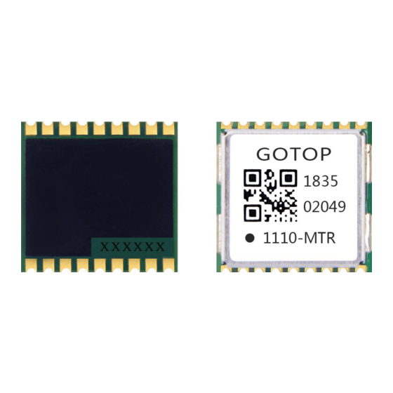
Figure: GT-1110-MTR Top View
MT3337 chip set
sensitivity: -165dBm
Track
Revision: V2.0.1-January 2015
Advertisement
Table of Contents

Related Manuals for Gotop GT-1110-MTR


Summary of Contents for Gotop GT-1110-MTR
- Page 1 GT-1110-MTR GPS Receiver Module General Description The Gotop GT-1110-MTR is a complete GPS engine module that features super sensitivity, ultra low power and small form factor. The GPS signal is applied to the antenna input of module, and a complete serial data message with position,...
-
Page 2: Table Of Contents
GT-1110-MTR GPS Receiver Module 1 Description..................................3 1.1 General Description...............................3 1.2. Key Features.................................4 1.3. Block Diagram..............................5 1.4. Protocols Supported by the Module........................5 2 Application..................................6 2.1. Pin Assignment..............................6 2.2. Pin Definition............................... 6 2.3. Power Supply............................... 8 2.4. Operating Modes..............................10 2.4.1. -
Page 3: Description
GPS, SBAS (including WAAS, EGNOS,MSAS, and GAGAN),QZSS, and AGPS. EASY technology as the key feature of GT-1110-MTR is one kind of AGPS. Capable collecting and processing all internal aiding information like GPS time,Ephemeris, Last Position,etc.,the GPS module delivers a very short TTFF in either Hot or Warm start. -
Page 4: Key Features
GT-1110-MTR GPS Receiver Module 1.2. Key Features Table 1: Key Features Parameter Specification • Power Supply Supply voltage: 2.8V~4.3V Typical: 3.3V • Acquisition: 25mA @VCC=VBAT=3.3V • Tracking: 20mA @VCC=VBAT=3.3V Power Consumption • Standby: 1.0mA @VCC=VBAT=3.3V • Backup: 7uA @VBAT=3.3V •... -
Page 5: Block Diagram
GPS Receiver Module 1.3. Block Diagram The following figure shows a block diagram of GT-1110-MTR module. It consists of a single chip GPS IC which includes the RF part and Baseband part, a LNA, a SAW filter, a TCXO, a crystal oscillator. -
Page 6: Application
GT-1110-MTR GPS Receiver Module 2 Application The module is equipped with a 18-pin SMT pad that connects to your application platform. Sub-interfaces included in the pad are described in details in the following chapters. 2.1. Pin Assignment Figure 2: Pin Assignment 2.2. - Page 7 GT-1110-MTR GPS Receiver Module UART Port Pin Name Pin No. Description DC Characteristics Comment VILmin=-0.3V VILmax=0.8V Receive data VIHmin=2.0V VIHmax=3.6V VOLmin=-0.3V VOLmax=0.4V Transmit data VOHmin=2.4V VOHmax=3.1V VILmin=-0.3V VILmax=0.8V If not used, this pin is left Receive data VIHmin=2.0V vacant. VIHmax=3.6V VOLmin=-0.3V...
-
Page 8: Power Supply
GT-1110-MTR GPS Receiver Module Figure 3: GPIO1/GPIO2 control circuit Table 3: Module baud rate control GPIO1(R1) GPIO2(R2) Baud rate state 9600bps 0Ω 4800bps 0Ω 115200bps 0Ω 0Ω 38400bps 2.3. Power Supply VCC pin supplies power for BB, RF, I/O, LNA, short protection and antenna detection circuit. The load current of VCC varies according to the VCC level, processor load, the number of tracked satellites and the rate of satellite re-acquisition. - Page 9 Power supply solutions for GT-1110-MTR module are listed as the following. The simplest power circuit for GT-1110-MTR module is 3.3V power source connected to VCC pin and VBAT pin of the module directly. In this case, once you powered on the module, the full cold start will be implemented.
-
Page 10: Operating Modes
Figure 6: Reference Charging Circuit for Chargeable Battery VCC does not supply power for RTC domain in GT-1110-MTR module, so the VBAT pin must be powered externally. Furthermore, it is strongly recommended to supply power to VBAT through a backup battery, which can ensure GT-1110-MTR module supports EASY technology and improves TTFF after next restart. -
Page 11: Full On Mode
Backup mode consumes lower power than standby mode. In this mode, only the backup supply VBAT is powered on while the main supply VCC is switched off by host or the TIMER signal of GT-1110-MTR. In order to enter into backup mode autonomously via the TIMER pin, an external switch circuit is necessary. - Page 12 When this command is executed successfully, TIMER signal will be pulled down to close the power switch, so GT-1110-MTR module can go into backup mode as the main power VCC is cut off. For this case, pulling the GPS_EN signal high by host is the only way to wake the module up.
-
Page 13: Periodic Mode
Figure 8: Seiko MS920SE Charge and Discharge Characteristics 2.4.4. Periodic Mode Periodic mode is a power saving mode of GT-1110-MTR that can control the full on mode and standby/backup mode periodically to reduce power consumption. It contains periodic standby mode and periodic backup mode. - Page 14 GT-1110-MTR GPS Receiver Module Example $PMTK225,1,3000,12000,18000,72000*16<CR><LF> $PMTK225,2,3000,12000,18000,72000*15<CR><LF> Sending “$PMTK225,0*2B” in any time will make the module enter into full on mode from periodic standby mode. Sending “$PMTK225,0*2B” just in Run_time or 2nd_run_time can make the module enter into full on mode from periodic backup mode.
-
Page 15: Alwayslocatetm Mode
“$PMTK225,0*2B” sent just after the module has been waked up from previous backup cycle. The positioning accuracy in AlwaysLocate mode will be somewhat degraded, especially in high speed. The ™ following picture shows the rough power consumption of GT-1110-MTR module in different daily scenes when AlwaysLocate mode is enabled. ™... -
Page 16: Flp Mode
FLP function is disabled by default. You can enable FLP by SDK or PMTK command. Sending “$PMTK262,1*29” will enable FLP function, and wait until GT-1110-MTR module gets a valid fix. Then wait at least 60s for GT-1110-MTR to enter FLP mode. FLP function will be disabled after sending “$PMTK262,0*28”. - Page 17 GT-1110-MTR GPS Receiver Module UART port: TXA: Send data to the RXD signal line of DTE. RXA: Receive data from the TXD signal line of DTE. Figure 11: Connection of Serial Interfaces This UART port has the following features: UART port can be used NMEA output and PMTK proprietary commands input.
-
Page 18: Easy Technology
EASY function is enabled by default. Command “$PMTK869,1,0*34” can be used to disable EASY. 2.7. Multi-tone AIC GT-1110-MTR module provides an advanced technology called multi-tone AIC (Active Interference Cancellation) to reject RF interference which comes from other active components on the main board. -
Page 19: Locus
Host can get the data from the module via UART by sending“$PMTK622,1*29”. The raw data which host gets has to be parsed via LOCUS parser code provided by GOTOP. For more details, please contact GOTOP technical supports. 2.9. PPS VS. NMEA Figure 13: PPS VS. -
Page 20: Antenna Interfaces
3.1. PCB Design Guide The GT-1110-MTR GPS receiver is designed for supporting the active antenna or passive antenna connected with pin RF_IN. The gain of active antenna should be no less than 15dB. The maximum noise figure should be no more than 2.5dB and output impedance is at 50 Ohm. - Page 21 GT-1110-MTR GPS Receiver Module Figure 15: Reference Design for Active Antenna C1, C2, L1 is used for power supply and filtering effect to the external active antenna, RF_IN antenna to a circuit part (BOLD line) for high frequency microstrip line, PCB in the design of this part of the line to calculate the characteristic impedance of the high-frequency line according to the principle of high frequency wiring.
-
Page 22: Electrical, Reliability And Radio Characteristics
GT-1110-MTR GPS Receiver Module 4 Electrical, Reliability and Radio Characteristics 4.1. Absolute Maximum Ratings Absolute maximum ratings for power supply and vol age on digital pins of the module are listed in the following table. Table 9: Absolute Maximum Ratings values within the specified boundaries by using appropriate protection diodes. -
Page 23: Current Consumption
In Hot Start, 15 seconds after First Fix. 4.4. Electrostatic Discharge GT-1110-MTR module is an ESD sensitive device. ESD protection precautions should still be emphasized. Proper ESD handling and packaging procedures must be applied throughout the processing, handling and operation of any application. -
Page 24: Reliability Test
GT-1110-MTR GPS Receiver Module 4.5. Reliability Test Table 13: Reliability Test Test Item Conditions Standard GB/T 2423.22-2002 Test Na Thermal Shock -30°C...+80°C, 144 cycles IEC 68-2-14 Na Damp Heat, Cyclic +55°C; >90% Rh 6 cycles for 144 hours IEC 68-2-30 Db Test 5~20Hz, 0.96m2/s3;... -
Page 25: Manufacturing, Packaging And Ordering Information
6.1. Assembly and Soldering GT-1110-MTR module is intended for SMT assembly and soldering in a Pb-free reflow process on the top side of the PCB. It is suggested that the minimum height of solder paste stencil is 100um to ensure sufficient solder volume. -
Page 26: Tape And Reel Packaging
GT-1110-MTR GPS Receiver Module 6.4. Tape and Reel Packaging Unit: mm Quantity per reel: 1000pcs Lengh per reel: 16m Figure 18: Tape and Reel Specifications Figure 19: Packaging physical Figure Table14: Reel Packaging Model Name MOQ for MP Minimum Package: 1000pcs Size: 365mm ×... -
Page 27: Appendix References
GT-1110-MTR GPS Receiver Module 7 Appendix References Table 15: Terms and Abbreviations Abbreviation Description AGPS Assisted GPS Active Interference Cancellation Circular Error Probable DGPS Differential GPS EASY Embedded Assist System EGNOS European Geostationary Navigation Overlay Service Extended Prediction Orbit Electrostatic Discharge... -
Page 28: Nmea 0183 Protocol
$GPxxx where xxx is a three-letter identifier of the message data that follows. NMEA messages have a check sum, which allows detection of corrupted data transfers. The Gotop GT-1110-MTR supports the following NMEA-0183 messages: $GPGGA, $GPGLL,$GPGSA,$GP GSV, $GPRMC and $GPVTG. - Page 29 GT-1110-MTR GPS Receiver Module 8.1 GGA-Global Positioning System Fixed Data $GPGGA, 161229.487,3723.2475,N, 12158.3416,W, 1,07,1.0,9.0,M.0000*18 Table 17: GGA Data Format Name Example Units Description Message ID $GPGGA GGA protocol header UTC Position 161229.487 hhmmss.sss Latitude 3723.2457 ddmm.mmmm N/S indicator N=north or S=south Longitude 12158.3416...
- Page 30 GT-1110-MTR GPS Receiver Module Table 18: GLL Data Format Name Example Units Description Message ID $GPGLL GLL protocol header Latitude 3723.2475 ddmm.mmmm N/S Indicator N=north or S=south Longitude 12158.3416 dddmm.mmmm E/W Indicator E=east or W=west UTC Position 161229.487 hhmmss.sss Status...
- Page 31 GT-1110-MTR GPS Receiver Module Table 19-2: Mode 2 Value Description Manual-forced to operate in 2D or 3D mode Automatic-allowed to automatically switch 2D/3D 8.4 GSV-GNSS Satellites in View $GPGSV , 2, 1, 07, 07, 79,048, 42, 02, 51,062, 43, 26, 36,256, 42, 27, 27, 138,42*71 $GPGSV, 2, 2, 07, 09, 23,313, 42, 04, 19, 159, 41, 15,12,041, 42*41.
- Page 32 GT-1110-MTR GPS Receiver Module Table 21: RMC Data Format Name Example Units Description Message ID $GPRMC RMC protocol header UTS Position 161229.487 hhmmss.sss Status A=data valid or V=data not valid Latitude 3723.2475 ddmm.mmmm N/S Indicator N=north or S=south Longitude 12158.3416 dddmm.mmmm...
- Page 33 (‘Gotop’). Information provided by Gotop is believed to be accurate and reliable. These materials are provided by Gotop as a service to its customers and may be used for informational purposes only. Gotop assumes no responsibility for errors or omissions in these materials, nor for its use. Gotop reserves the right to change specification at any time without notice.
Need help?
Do you have a question about the GT-1110-MTR and is the answer not in the manual?
Questions and answers