Table of Contents
Advertisement
Quick Links
CAUTION, MICROWAVE RADIATION ............................................................................................................... 1
WARNING ............................................................................................................................................................ 1
PRODUCT SPECIFICATIONS ........................................................................................................................... 2
GENERAL INFORMATION .................................................................................................................................. 2
APPEARANCE VIEW ......................................................................................................................................... 3
OPERATION SEQUENCE .................................................................................................................................. 4
FUNCTION OF IMPORTANT COMPONENTS .................................................................................................. 5
SERVICING ......................................................................................................................................................... 6
TEST PROCEDURE ........................................................................................................................................... 8
TOUCH CONTROL PANEL ............................................................................................................................... 14
COMPONENT REPLACEMENT AND ADJUSTMENT PROCEDURE ............................................................. 18
MICROWAVE MEASUREMENT ...................................................................................................................... 24
WIRING DIAGRAM ........................................................................................................................................... 25
PICTORIAL DIAGRAM ..................................................................................................................................... 26
CONTROL PANEL CIRCUIT ............................................................................................................................. 27
PRINTED WIRING BOARD ............................................................................................................................... 28
PARTS LIST ..................................................................................................................................................... 29
SERVICE MANUAL
MODELS
In interests of user-safety the oven should be restored to its original
condition and only parts identical to those specified should be used.
TABLE OF CONTENTS
SHARP CORPORATION
MICROWAVE OVEN
R-241CWAA
R-241CWAC
R-241CWAP
R-241CWAA
R-241CWAC
R-241CWAP
S7908R241CPA/
(Argentina)
(Chile)
(Peru)
Advertisement
Table of Contents

Related Manuals for Sharp R-241CWAA


Summary of Contents for Sharp R-241CWAA
-
Page 1: Table Of Contents
R-241CWAA R-241CWAC R-241CWAP SERVICE MANUAL S7908R241CPA/ MICROWAVE OVEN R-241CWAA MODELS (Argentina) R-241CWAC (Chile) R-241CWAP (Peru) In interests of user-safety the oven should be restored to its original condition and only parts identical to those specified should be used. TABLE OF CONTENTS CAUTION, MICROWAVE RADIATION ....................... - Page 2 R-241CWAA R-241CWAC R-241CWAP...
-
Page 3: Caution Microwave Radiation
R-241CWAC (Chile) R-241CWAP (Peru) GENERAL IMPORTANT INFORMATION APPEARANCE VIEW This Manual has been prepared to provide Sharp Corp. Service engineers with Operation and Service Information. It is recommended that service engineers carefully study the OPERATING SEQUENCE entire text of this manual, so they will be qualified to render satisfactory customer service. -
Page 4: Product Specifications
Set Weight (Approx.) 14 kg GENERAL INFORMATION WARNING THIS APPLIANCE MUST BE EARTHED IMPORTANT THE WIRES IN THIS MAINS LEAD ARE COLOURED IN ACCORDANCE WITH THE FOLLOWING CODE: GREEN-AND-YELLOW (for R-241CWAA & R-241CWAC): EARTH BLUE : NEUTRAL BROWN : LIVE... -
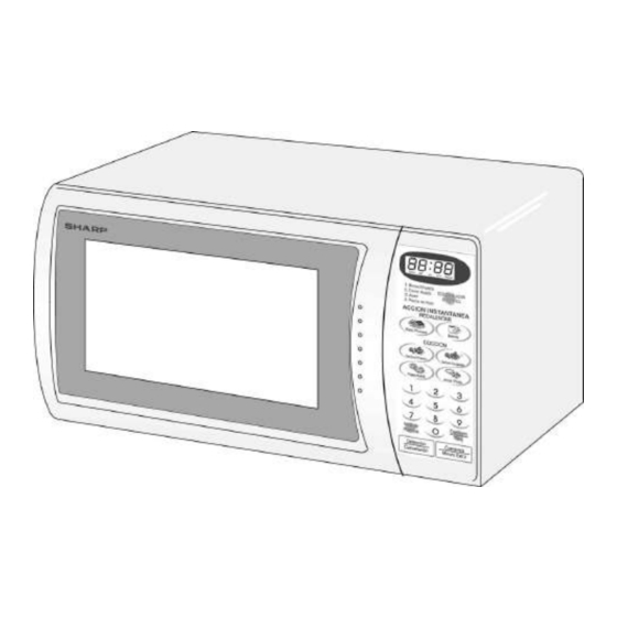
Page 5: Appearance View
R-241CWAA R-241CWAC R-241CWAP APPEARANCE VIEW OVEN 1. Ventilation openings 8. Control panel 2. Oven lamp 9. Waveguide cover 3. Door hinges 10. Power supply cord 4. Door safety latches 11. Turntable 5. See through door 12. Roller stay 6. Door seals sealing surfaces 13. -
Page 6: Operation Sequence
R-241CWAA R-241CWAC R-241CWAP OPERATION SEQUENCE The circuits to the power transformer, fan motor and OFF CONDITION turntable motor are cut off when the 1st. latch switch and Closing the door activates all door interlock switches 2nd. interlock relay control switch are made open. -
Page 7: Function Of Important Components
R-241CWAA R-241CWAC R-241CWAP FUNCTION OF IMPORTANT COMPONENTS DOOR OPEN MECHANISM HIGH VOLTAGE FUSE The door is opened by pulling the door, refer to the Figure D- The high voltage fuse blows when the high voltage rectifier or the magnetron is shorted. -
Page 8: Servicing
Sharp recommend that wherever possible fault-finding is carried out with the supply disconnected. It may in, some cases, be necessary to connect the supply after the outer... - Page 9 R-241CWAA R-241CWAC R-241CWAP CK = Check / RE = Replace TEST PROCEDURE A B C D E E E F G G H H I K M N RE CK CK RE CK CK CK CK CK POSSIBLE CAUSE DEFECTIVE PARTS...
-
Page 10: Test Procedure
R-241CWAA R-241CWAC R-241CWAP TEST PROCEDURES PROCEDURE COMPONENT TEST LETTER MAGNETRON TEST NEVER TOUCH ANY PART IN THE CIRCUIT WITH YOUR HAND OR AN INSULATED TOOL WHILE THE OVEN IS IN OPERATION. CARRY OUT 3D CHECKS. Isolate the magnetron from the high voltage circuit by removing all leads connected to the filament terminal. - Page 11 R-241CWAA R-241CWAC R-241CWAP TEST PROCEDURES PROCEDURE COMPONENT TEST LETTER Initial temperature ....................T1 = 11°C Temperature after (52 + 2) = 54 sec..............T2 = 21°C Temperature difference Cold-Warm ..............∆T1 = 10°C Measured output power The equation is “P = 80 x ∆T” ............P = 80 x 10°C = 800 Watts ±...
- Page 12 R-241CWAA R-241CWAC R-241CWAP TEST PROCEDURES PROCEDURE COMPONENT TEST LETTER HIGH VOLTAGE CAPACITOR TEST CARRY OUT 3D CHECKS. A. Isolate the high voltage capacitor from the circuit. B. Continuity check must be carried out with measuring instrument which is set to the highest resistance range.
- Page 13 R-241CWAA R-241CWAC R-241CWAP TEST PROCEDURES PROCEDURE COMPONENT TEST LETTER An open circuit thermal cut-out (MG) indicates that the magnetron has overheated, this may be due to resistricted ventilation, cooling fan failure or a fault condition within the magnetron or HV circuit.
- Page 14 R-241CWAA R-241CWAC R-241CWAP TEST PROCEDURES PROCEDURE COMPONENT TEST LETTER a) When touching the pads, a certain pad produces no signal at all. b) When touching a number pad, two figures or more are displayed. c) When touching the pads, sometimes a pad produces no signal.
- Page 15 R-241CWAA R-241CWAC R-241CWAP TEST PROCEDURES PROCEDURE COMPONENT TEST LETTER DC. voltage indicated ..Defective relay. DC. voltage not indicated ..Check diode which is connected to the relay coil. If diode is good, control unit is defective. RELAY SYMBOL OPERATIONAL VOLTAGE CONNECTED COMPONENTS Approx.
-
Page 16: Touch Control Panel
R-241CWAA R-241CWAC R-241CWAP TOUCH CONTROL PANEL ASSEMBLY OUTLINE OF TOUCH CONTROL PANEL 3) Power Source Circuit The touch control section consists of the following units as This circuit generates voltage necessary in the control shown in the touch control panel circuit. - Page 17 H : GND H : GND L : -5V L : -5V R-241CWAA/ R-241CWAC R-241CWAP (Peru) Oven lamp, fan motor and turntable motor driving signal. To turn on and off shut off relay (RY1). The square waveform voltage is delivered to the RY1 driving circuit and RY2 control circuit.
- Page 18 R-241CWAA R-241CWAC R-241CWAP Pin No. Signal Description Terminal not used. INT2 Signal synchronized with commercial power source frequency. This is the basic timing for time processing of LSI. H : GND H : GND L : -5V L : -5V 16.7 msec...
- Page 19 R-241CWAA R-241CWAC R-241CWAP SERVICING 1. Precautions for Handling Electronic Components B. On some models, the power supply cord between This unit uses CMOS LSI in the integral part of the the touch control panel and the oven proper is so circuits.
-
Page 20: Component Replacement And Adjustment Procedure
Oven lamp, Magnetron, High voltage transformer ners. and Oven cavity. 1. Before wiring, 3) Sharp edge: 1) Disconnect the power supply. Bottom plate, Oven cavity, Waveguide flange, Chas- 2) Open the door and wedge the door open. sis support and other metallic plate. - Page 21 R-241CWAA R-241CWAC R-241CWAP HIGH VOLTAGE COMPONENTS REMOVAL (HIGH VOLTAGE CAPACITOR, HIGH VOLTAGE RECTIFIER ASSEMBLY AND H.V. FUSE) 8. Disconnect the H.V. fuse from the high voltage capacitor. To remove the components, proceed as follows. 9. Now H.V. rectifier assembly, H.V. fuse and H.V. capaci- 1.
- Page 22 2. Install the earth wire lead of power supply cord to the oven 2. Remove the single (1) screw holding the green/yellow cavity back plate with one (1) screw and tight the screw (for wire to the oven cavity back plate (for R-241CWAA/ R- R-241CWAA/ R-241CWAC). 241CWAC).
- Page 23 R-241CWAA R-241CWAC R-241CWAP FAN MOTOR REPLACEMENT 14. Remove the two (2) screws holding the fan motor to the REMOVAL fan duct. 1. CARRY OUT 3D CHECKS. 15. Now, the fan motor is free. 2. Disconnect the wire leads from the fan motor.
- Page 24 R-241CWAA R-241CWAC R-241CWAP 1ST. LATCH SWITCH, 2ND. INTERLOCK RELAY CONTROL SWITCH AND MONITOR SWITCH REMOVAL in the upper position. 1. CARRY OUT 3D CHECKS. 2. Re-connect wire leads to each switch. Refer to chapter 2. Disconnect wire leads from the switches and control panel.
- Page 25 R-241CWAA R-241CWAC R-241CWAP DOOR REPLACEMENT REMOVAL 1. Door latch heads smoothly catch latch hook through 1. Disconnect the power supply cord. latch holes and that latch head goes through center of 2. Open the door slightly. latch hole. 2. Deviation of door alignment from horizontal line of cavity 3.
-
Page 26: Microwave Measurement
R-241CWAA R-241CWAC R-241CWAP MICROWAVE MEASUREMENT After adjustment of door latch switches, monitor switch and Recommended instruments are: door are completed individually or collectively, the following NARDA 8100 leakage test must be performed with a survey instrument NARDA 8200 and it must be confirmed that the result meets the require- HOLADAY HI 1500 ments of the performance standard for microwave oven. -
Page 27: Wiring Diagram
R-241CWAA R-241CWAC R-241CWAP SCHEMATIC NOTE: CONDITION OF OVEN 1. DOOR CLOSED. 2. CLOCK APPEARS ON DISPLAY. NOTE: " " indicates components with potential above 250V. THERMAL R-241CWAA for R-241CWAP CUT-OUT 95˚C (MG) R-241CWAC (Peru) COM. N.O. CAPACITOR 0.94µF AC2000V for R-241CWAP (Peru) 2ND. -
Page 28: Pictorial Diagram
R-241CWAA R-241CWAC R-241CWAP... -
Page 29: Control Panel Circuit
R-241CWAA R-241CWAC R-241CWAP... -
Page 30: Printed Wiring Board
R-241CWAA R-241CWAC R-241CWAP (J7) (J5) (J3) (J6) (J4) (J2) (J1) CN - B DOOR SW AC (N) FM TTM Figure S-3. Printed Wiring Board... -
Page 31: Parts List
1st. latch switch & 2nd. interlock relay control switch 1- 2 QSW-MA132WRE0 Monitor switch 1- 3 QACC-A102WRE0 Power supply cord for Argentina [R-241CWAA] 1- 3 QACC-A077WRE0 Power supply cord for Chile [R-241CWAC] 1- 3 QACC-A058WRE0 Power supply cord for Peru [R-241CWAP]... - Page 32 6- 4 FW-VZB605WRE0 Switch harness 6- 5 FW-VZB688WRE0 Main wire harness 6- 6 TCAUAA247WRR0 Argentina caution label for Argentina [R-241CWAA] 6- 6 TCAUHA214WRR0 K caution label for Chile [R-241CWAC] 6- 6 TCAUHA214WRR0 K caution label for Peru [R-241CWAP] 6- 7...
- Page 33 6-14 TLABSA073WRR0 N label for Argentina [R-241CWAA] SCREWS AND WASHERS 7- 1 XHPSD40P08K00 Screw : 4mm x 8mm for Argentina [R-241CWAA] 7- 1 XHPSD40P08K00 Screw : 4mm x 8mm for Chile [R-241CWAP] 7- 1 XHPSD40P08K00 Screw : 4mm x 8mm for Peru [R-241CWAP]...
- Page 34 R-241CWAA R-241CWAC R-241CWAP OVEN AND CABINET PARTS 1-13 7-12 1-16 4-14 1-15 1-17 6-11 1-11 6-10 6-13 4-11 6-12 1-14 4-13 7-11 4-10 1-10 4-12 1-12 7-10 7-10...
- Page 35 R-241CWAA R-241CWAC R-241CWAP Before attaching Control unit to Control panel, foil side of Control CONTROL PANEL PARTS unit must be cleaned by ethyl- alcohol. 3-2-2 DOOR PARTS 3-2-1 MISCELLANEOUS Actual wire harness may be different than illustration.
- Page 36 R-241CWAA R-241CWAC R-241CWAP '99SHARP CORP. (7S0.120E) Printed in U.S.A.
Need help?
Do you have a question about the R-241CWAA and is the answer not in the manual?
Questions and answers