Table of Contents
Advertisement
Quick Links
1
5
5
0
n
m
1
5
5
0
n
m
A
m
p
l
i
f
A
m
p
l
i
f
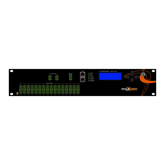
Sample Illustrations of MXA54 Series
Available in several configurations, sizes, and number of output ports
E
r
b
i
u
m
D
E
r
b
i
u
m
D
·
·
i
e
r
M
X
-
A
i
e
r
M
X
-
A
M
u
l
t
i
-
P
o
M
u
l
t
i
-
P
o
O
p
e
r
a
t
o
r
G
O
p
e
r
a
t
o
r
G
o
p
e
d
F
i
b
o
p
e
d
F
i
b
5
4
S
e
r
i
e
5
4
S
e
r
i
e
r
t
r
t
u
i
d
e
u
i
d
e
e
r
e
r
s
s
Advertisement
Table of Contents

Related Manuals for Maxcom MX-A54 Series


Summary of Contents for Maxcom MX-A54 Series
- Page 1 · · Sample Illustrations of MXA54 Series Available in several configurations, sizes, and number of output ports...
-
Page 2: Product Summary
PRODUCT SUMMARY The Maxcom MXA54 Erbium Doped Fiber Amplifier (EDFA) has been designed for CATV, FTTH and HFC applications. The EDFA is suitable for long haul transmission networks or FTTH distribution networks. This optical amplifier is packaged in a 19” rack mount housing to provide a complete optical communications solution. -
Page 3: Fiber Connections
E. Clean Optical Connectors before use. Fiber Connections Cleaning fiber-optic connectors can help prevent interconnect problems and therefore, aid system performance. When optical connectors are disconnected and reconnected, the fiber surface may become dirty or scratched. The goal of cleaning the fiber optic connectors is to remove all dust and contaminants without leaving any residue. - Page 4 Operation of the panel Indicator lamps PUMP- Status lamp Red INPUT- Status lamp Red ALARM - Status lamp Red POWER1 - Status lamp Green (no light when power is off) POWER2 - Status lamp Green (no light when power is off) Start-up main menu Press \...
-
Page 5: Modifying Settings
Power1 Read-only menu, displays the status of power1 Power2 Read-only menu, displays the status of power2 Unit Temp Read-only menu, display temperature of the unit Adjustable list, IP address setting menu Adjustable parameter, subnet mask setting menu Adjustable parameter, gateway address setting menu Adjustable parameter, trap address setting menu Adjustable parameter, trap address setting menu LCD Contrast Level... - Page 6 Maxcom EDFA’s are available in many configurations based on the customers request and the requested connector types. The drawings below illustrate the various forms and connector types. This provides a very flexible platform to accommodate most customer requirements.
-
Page 7: Port And Cable Assignments
PORT AND CABLE ASSIGNMENTS The MXA54 series provides the following management port: RS232 port: suitable for examining the MXA54 parameters and system configuration by a PC RS232 port. SNMP: Simple network management protocol. Before connecting the MXA54 series to a port, please read the following instructions and port connectivity requirements. -
Page 8: Port Connection
Workstation port Input receive data+ Output transmit data+ Input receive data- Output transmit data- Output transmit data+ Input receive data+ Output transmit data- Input receive data- 4, 5, 7, 8 Nonuse Nonuse Table 4-1 RJ-45 Pin assignment Straight Cross (HA5400) (Adapter) (HA5400) (HUB/ HA5400) - Page 9 3) Plug one end of the cable into the PC's NIC and plug the other end into any RJ-45 port of the MXA54 series. All the MXA54 RJ-45 ports support both 10Mbps and 100Mbps Ethernet connections. Ensure that the plug's locking tab clicks into proper position to make good connection.
-
Page 10: Pin Assignment
Pin assignment Figure 4-2.2 DB9/RS232 pin assignment Distribution RXD: accepting of data TXD: transmitter data SG: signal Table 4-3 Pin information FAULT DISPOSAL The MXA54 series FTTP EDFA can monitor system operation and offer brief notices of warnings and can correct the majority of status deflections of the equipment, such as: system parameter floating, equipment tolerance, laser aging, level changes, and temperature changes. -
Page 11: Warning Status
The alarm may be eliminated by restarting the power supply or resetting the power. If the user is unable to eliminate the alarm, please contact Maxcom. Fault prevention Please read the below information to prevent potential problems. - Page 12 Available 64 ports Output Power Range: +15 to +23 dBm Please consult with your Maxcom Rep for ordering *Notes: Output Monitor port - Included options, *Note - Some options only available of certain Adjustable Output feature - Included chassis or models...
Need help?
Do you have a question about the MX-A54 Series and is the answer not in the manual?
Questions and answers