Table of Contents
Advertisement
Quick Links
1
5
5
0
1
5
5
0
A
m
p
A
m
p
CONTENT
1.0
1.0
1.1
2.0
2.0
3.0
2.1
THE OPERATION OF THE PANEL
4.0
3.0
5.0
3.1
6.0
3.2
7.0
4.0
8.0
n
m
E
r
b
i
u
m
n
m
E
r
b
i
u
m
l
i
f
i
e
r
M
X
-
l
i
f
i
e
r
·
M
X
-
·
U
S
E
R
M
a
U
S
E
R
M
a
www.maxcomcorp.com
D
o
p
e
d
F
i
b
e
D
o
p
e
d
F
i
b
e
A
5
1
0
0
S
e
r
i
e
A
5
1
0
0
S
e
r
i
e
n
u
a
l
n
u
a
l
Ver. 1.0sb
r
r
s
s
Advertisement
Table of Contents

Related Manuals for Maxcom MX-A5100 Series


Summary of Contents for Maxcom MX-A5100 Series
- Page 1 Ver. 1.0sb · · CONTENT PRODUCT SUMMARY PRODUCT SUMMARIZE AMPLIFIER CONTROLS, INDICATORS, AND ALARMS THE OPERATION OF THE PANEL EQUIPMENT OPERATION PRINCIPLE A5100 SERIES AMPLIFIER CIRCUIT PRINCIPLE C/R INFERIORITY RATE DESCRIPTION OF STATUS ALARM www.maxcomcorp.com...
- Page 2 CATV, FTTH and HFC applications. The EDFA is suitable for long haul transmission networks or FTTH distribution networks. The MX-A5100 series is a CATV booster EDFA has a gain spectrum band within 1540~1565nm. It is designed for the application of single channel, or 1~8 continuous ribbon channels (ITU wavelength).
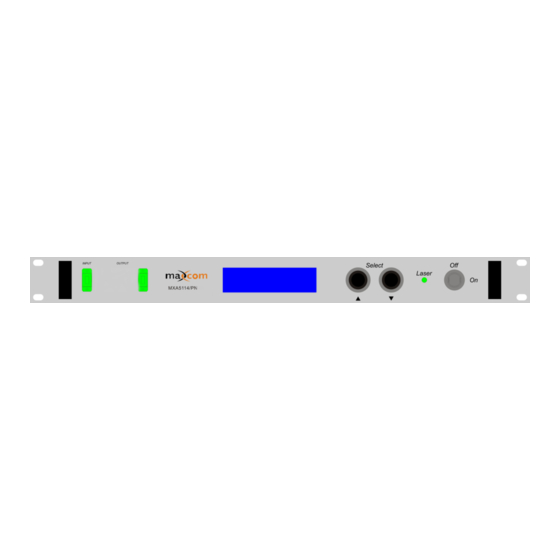
- Page 3 The operation of the control panel 10.1.1 Open menu Plug in the power supply Turn on power switch in the rear panel, and turn on the laser key or on/off switch in the front panel Front panel displays “KEY ON…”. Laser status lamp turns green from red, and the unit enters a self-diagnostic mode.
- Page 4 Menu # 10 - PUMP TEMP1 Read-only menu, displays the temperature of pump Menu # 11 - PUMP TEMP2 Read-only menu, displays the temperature of pump Menu # 12 - +5V Reads Read-only menu, displays the voltage +5V Menu # 13 - -5V Reads Read-only menu, displays the voltage -5V Menu # 14 - UNIT TEMP Read-only menu, displays the temperature of chassis...
- Page 5 +5Vvoltage(+5V READS) >±0.5V alarm. -5Vvoltage(-5V READS) >±0.5V alarm. Press ▲\▼ key to amend the IP address menu that needs to be amended. Press ▲▼ at the same time to enter the menu, press ▼ to choose the amended place, push ▲ to amend, and then press ▲▼...
- Page 6 11.2 C/R inferiority rate ( ) Amplifier input power(dBm) 12.0 DESCRIPTION OF STATUS ALARM Working status indication (LED) is near the power supply switch in the front panel. When it is green, the device is working properly; when it is red, the laser does not operate;...
Need help?
Do you have a question about the MX-A5100 Series and is the answer not in the manual?
Questions and answers