Table of Contents
Advertisement
Advertisement
Table of Contents

Summary of Contents for Vaillant FM5
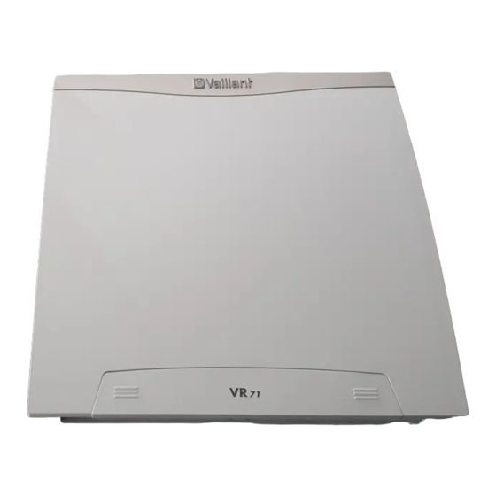
- Page 1 FM5 functional module VR 71 en Installation instructions...
-
Page 2: Table Of Contents
Installation instructions Contents Safety ..............3 Intended use ............3 General safety information ........3 Regulations (directives, laws, standards) ....4 Notes on the documentation ......5 Observing other applicable documents ....5 Storing documents..........5 Validity of the instructions ........5 Product description.......... -
Page 3: Safety
Safety General safety information 1.2.1 Risk caused by inadequate Intended use qualifications In the event of inappropriate or improper use, The following work must only be carried out damage to the product and other property by competent persons who are sufficiently may arise. -
Page 4: Regulations (Directives, Laws, Standards)
Regulations (directives, laws, standards) ▶ Observe the national regulations, stand- ards, directives, ordinances and laws. Installation instructions 0020197272_02... -
Page 5: Notes On The Documentation
Product description Switching capacity for each relay and overall switching Nomenclature used capacity – FM5 or FM5 functional module: Instead of VR 71 CE marking – System control: Instead of VRC 700 / VRC 720 Design of the product ... -
Page 6: Removing The Front Casing
Line length Installing the front casing ≤ 50 m Sensor lines Mount the front casing at the top of the wall socket. ≤ 125 m Use the fixing screw to secure the front casing. Bus lines Slide the cover over the fixing screw until the cover Removing the front casing clicks into place. -
Page 7: Decommissioning
Connecting the line to the lower terminal block Danger! Risk of damage caused by incorrect in- stallation. Connecting wires that have been stripped too far may cause short circuits and damage the electronics if a strand accidentally comes loose. ▶ Only strip the outer sheathing of flexible ducts to a maximum of 2.5 cm to prevent short circuits. -
Page 8: Customer Service
Disposing of the product If the product is labelled with this symbol: ▶ In this case, do not dispose of the product with the household waste. ▶ Instead, hand in the product to a collection centre for waste electrical or electronic equipment. Disposing of batteries If the product contains batteries that are labelled with this symbol:... - Page 12 Supplier Vaillant Ltd. Nottingham Road Belper Derbyshire DE56 1JT Telephone 0330 100 3143 info@vaillant.co.uk www.vaillant.co.uk 0020197272_02 Publisher/manufacturer Vaillant GmbH Berghauser Str. 40 D-42859 Remscheid Tel. +49 2191 18 0 Fax +49 2191 18 2810 info@vaillant.de www.vaillant.de © These instructions, or parts thereof, are protected by copyright and may be reproduced or distributed only with the manufacturer's written consent.


Need help?
Do you have a question about the FM5 and is the answer not in the manual?
Questions and answers