Table of Contents
Advertisement
Quick Links
Advertisement
Table of Contents

Related Manuals for Vision Components VCSBC4018


Summary of Contents for Vision Components VCSBC4018
- Page 1 Vision Components The Smart Camera People VCSBC4018 Manual Hardware and Programming Manual for VCSBC4018 Revision 2.0 July 2005 Document name: VCSBC4018.pdf © Vision Components GmbH Ettlingen, Germany © 1996-2005 Vision Components GmbH Ettlingen, Germany...
- Page 2 Foreword and Disclaimer This documentation has been prepared with most possible care. However Vision Components GmbH does not take any liability for possible errors. In the interest of progress, Vision Components GmbH reserves the right to perform technical changes without further notice.
-
Page 3: Table Of Contents
4.3.1 Pin Assignments J3 camera socket 4.3.2 Electrical specifications digital IO s J3 interface 4.3.3 Electrical specifications of the VCSBC4018 Power Supply J3 interface 4.3.4 Matching connector and cable for J3 camera socket J4: Ethernet Interface 4.4.1 Pin Assignments J4 camera socket 4.4.2... -
Page 4: General Information
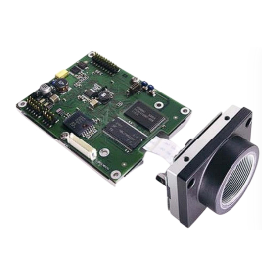
(standard delivery) The VCSBC4018 is one of the fastest Smart Cameras on the market – designed for demanding OEM applications. The computational power of 3200 MIPS on a 60 by 80mm circuit board is equal to a 2.6 GHZ Pentium PC. -
Page 5: Basic Structure
The image is stored in SDRAM memory using one of the 64 DMA channels (EDMA). Unlike most other Vision Component Smart Cameras, the VCSBC4018 does not have a direct video output. However if monitoring of the camera image is required, this can be done by downloading via “Image Transfer”... -
Page 6: Technical Specifications Vcsbc4018
Illumination Enable LVTT output, Duration / Boost LVTTL output Ethernet interface: 100 Mbit CE certification: No CE Certification from Vision Components as the OEM customer is required to certify entire system (including housing, cabling, etc.). Storage Conditions Temperature: -20 to 60 deg C, Max. humidity: 90%, non condensing. -
Page 7: Camera Interfaces
The pin assignments, electrical specifications as well as available accessories are shown for each interface connector in the following sections: Deviating from the image, the VCSBC4018 is now shipped with a wall plug with center polarization slot. © 1996-2005 Vision Components GmbH Ettlingen, Germany... -
Page 8: J1 : Illumination Interface
Available accessories for this J1 camera socket www.jst.com Part number of the J1 socket: 04FM-1.0BP-TF , manufactured by JST ( The matching flat cable (at 38mm length) for this connector can be ordered from Vision Components: Order number: Ek000377 © 1996-2005 Vision Components GmbH Ettlingen, Germany... -
Page 9: J2: Expansion Port / Trigger Interface
VCSBC4018.pdf – Hardware Documentation VCSBC4018 Smart Camera 4.2 J2: Expansion Port / Trigger Interface 4.2.1 Pin Assignments J2 camera socket Pin Number Signal I2C_Clock I2C_Data Trig_in Trig_out Vcc (3.3V) Pin Locations 10 12 14 16 18 20 11 13 15 17 19 ∇... -
Page 10: Electrical Specifications J2 Camera Socket
VCSBC4018.pdf – Hardware Documentation VCSBC4018 Smart Camera 4.2.2 Electrical specifications J2 camera socket All Signals are Low Level TTL (3.3V), not opto isolated. The following Signals have a 4k7 pull up resistor on board: I2C_Clock I2C_Data Trig_in Trigger IO Specifications: The board features a dedicated fast TTL trigger input (for use as image capture trigger) and a fast TTL trigger output (as strobe-light trigger). -
Page 11: Matching Connector And Cable For J2 Camera Socket
Alternatively an additional 12 pin Power Supply /PLC and a 8 pin Ethernet cable (Cable set for VCSBC4018, VK000229 see section 5) can be used next to each other to cover all contacts. Since only pin 1,2,5 and 6 of the 8 pin Ethernet connector are connected, place these two plugs on the J2... -
Page 12: J3: Power Supply And Io Interface
VCSBC4018.pdf – Hardware Documentation VCSBC4018 Smart Camera 4.3 J3: Power Supply and IO Interface The J3 connector includes the camera power supply and the digital IOs. 4.3.1 Pin Assignments J3 camera socket Pin Number Signal J3 Standard Out0 VCSBC4018 socket:... - Page 13 VCSBC4018.pdf – Hardware Documentation VCSBC4018 Smart Camera Input Signals IO interface Nominal voltage: 12 – 24 V Absolute maximum voltage: voltages greater than 40 V can destroy the inputs Type: Circuit GND directly connected Input current: 1 mA @ 24V...
-
Page 14: Electrical Specifications Of The Vcsbc4018 Power Supply J3 Interface
VCSBC4018.pdf – Hardware Documentation VCSBC4018 Smart Camera 4.3.3 Electrical specifications of the VCSBC4018 Power Supply J3 interface Nominal Voltage: 12V – 24V Nominal Power Consumption 2.4W Minimum operational voltage (including ripple): Minimum Operating voltage and corresponding current: 200mA Maximum Operating voltage and corresponding... -
Page 15: Matching Connector And Cable For J3 Camera Socket
The wall socket with polarization slot has been used for this camera in order to avoid camera damage caused by shifted or reversed plug connections. The standard VCSBC50 cable can be used to prevent shifted plug mounting: Color code VCSBC50/ VCSBC4018 Power / PLC Cable VC000173: Pin Number Signal... -
Page 16: J4: Ethernet Interface
VCSBC4018.pdf – Hardware Documentation VCSBC4018 Smart Camera 4.4 J4: Ethernet Interface 4.4.1 Pin Assignments J4 camera socket Pin Number Signal TXD+ TXD- RXD+ RXD- Pin locations: ∇ 4.4.2 Electrical specifications J4 camera interface The Ethernet interface is decoupled from the rest of the circuit with a 1.5kV insulation transformer. For all connection specifications refer to the Ethernet standard. -
Page 17: Matching Connector And Cable For J4 Camera Socket
VCSBC4018.pdf – Hardware Documentation VCSBC4018 Smart Camera 4.4.3 Matching connector and cable for J4 camera socket Socket J4 on circuit board: Part number: 87759-0850, manufacturer: Molex Matching connector: Part number: 51110-0850, manufacturer: Molex There are two different cables now available for the J4 Ethernet interface: 1. -
Page 18: J6: Emulator Interface
VC provides an adaptor cable that connects the J6 Emulator socket with the Jtag Emulator connector. 80mm JST Plug 14 pin connector for J6 For Jtag module socket Order Number for the J6 /JTAG Adaptor cable from Vision Components: VK000248 © 1996-2005 Vision Components GmbH Ettlingen, Germany... -
Page 19: Accessories
For interface cables and connectors available also consult the corresponding section in chapter 4 of this manual. The VCSBC4018 can be used with 12mm threaded micro lenses or C-mount lens holder. Due to the different options these lens holders have to be ordered separately to the camera. If ordered together, VC ships the camera fully assembled. -
Page 20: Programming Vcsbc4018 Cameras
VCSBC4018.pdf – Hardware Documentation VCSBC4018 Smart Camera 6 Programming VCSBC4018 Cameras The VCSBC4018 operating system includes some additional functions, mainly for the control of the additional interfaces. Without direct VGA output some video control functions are not implemented for this camera. -
Page 21: Ethernet Communication
VCSBC4018.pdf – Hardware Documentation VCSBC4018 Smart Camera 6.2 Ethernet Communication The default camera IP address is 192.168.0.65 – as with all Ethernet cameras from VC. The IP address can be changed to a different loading a #IP file into camera memory. - Page 22 Calling VCnet for a camera with serial number S/N = 100000: C:\>java -jar vcnet.jar -snr 100000 Corresponding print out of camera response via Telnet Port 23: VCnet Recovering Tool Version 1.0 - Copyright Vision Components 2005 Recovering Serial Number = 100000 Listening on port 67 for incoming packets! Packet 2 from: /0.0.0.0...
-
Page 23: Special Vcrt Functions For Programming Vcsbc4018 Cameras
VCSBC4018.pdf – Hardware Documentation VCSBC4018 Smart Camera 6.5 Special VCRT functions for programming VCSBC4018 cameras 6.5.1 Trigger Functions The trigger works like with the VC20XX cameras. Please refer to the VCRT5.pdf manual – available form the Registered User Area of the VC website. -
Page 24: Controlling The Illumination Interface J1
Controlling the Illumination Interface J1 The Illumination Interface has proven useful with the VCSBC50 camera and has therefore been also integrated into the VCSBC4018. Due to the different processor, the use of this interface is slightly different. There are two different modes for switching the Illumination Enable Signal (Pin 3, J1). - Page 25 VCSBC4018.pdf – Hardware Documentation VCSBC4018 Smart Camera Appendix A: Block diagram VCSBC4018 Smart Camera 4 MB Flash Eprom C64XX 32 MB SDRAM Bus Controller Trigger In/ Out Trigger In/ CCD - A/D Con- FIFO Sensor verter Control/ Status Reg. Driver...
- Page 26 VCSBC4018.pdf – Hardware Documentation VCSBC4018 Smart Camera Appendix C: Overall Dimensions VCSBC4018 35.4 ≈ 13 63.2 ≈ 81.3 Note: the sensor head protrudes the circuit board slightly when mounted as shown! Tolerances: All vertical dimensions: +/- 0.5mm. All horizontal dimensions: +/- 0.1mm.
- Page 27 VCSBC4018.pdf – Hardware Documentation VCSBC4018 Smart Camera Appendix E: Drawing Camera Head VCSBC4018 Tolerances: All dimensions: +/- 0.1mm © 1996-2005 Vision Components GmbH Ettlingen, Germany...
- Page 28 Appendix F: Spectral Transmission of IR Filter Note: This IR cut filter is incorporated in every VCSBC4018 camera with C- mount lens holder. The IR filter can be removed if required. In this case, special care must be taken not to damage the CCD sensor.
- Page 29 VCSBC4018.pdf – Hardware Documentation VCSBC4018 Smart Camera Index Accessories ........19 Plug Assigment Rail Mount Power Adapter ......19 Overview ............. 7 Autoexec........21 Power Adapter CCD ..........5 Rail Mount ..........19 Clear glass protective sensor window . 19 Power and IO Connector..... 7 Code Composer Studio.....
Need help?
Do you have a question about the VCSBC4018 and is the answer not in the manual?
Questions and answers