Advertisement
Overview
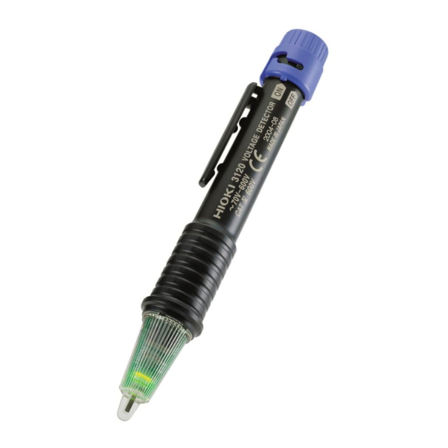
This noncontact type of voltage detector unit enables the hot-line state of AC voltage to be checked through the wire or cable covering.
Initial Inspection
When you receive the instrument, inspect it carefully to ensure that no damage occurred during shipping. If damage is evident, or if it fails to operate according to the specifications, contact your dealer or Hioki representative.
Maintenance and Service
- To clean the instrument, wipe it gently with a soft cloth moistenedwith water or mild detergent. Never use solvents such as benzene, alcohol, acetone, ether, ketones, thinners or gasoline, as they can deform and discolor the case.
- If the instrument seems to be malfunctioning, confirm that thebatteries are not discharged, before contacting your dealer or Hioki representative.
Safety
This manual contains information and warnings essential for safe operation of the instrument and for maintaining it in safe operating condition. Before using it, be sure to carefully read the following safety precautions.

This instrument is designed to comply with IEC 61010 Safety Standards, and has been thoroughly tested for safety prior to shipment. However, mishandling during use could result in injury or death, as well as damage to the instrument. Be certain that you understand the instructions and precautions in the manual before use.
We disclaim any responsibility for accidents or injuries not resulting directly from instrument defects.
Safety Symbol
 | In the manual, the symbol indicates particularly important information that the user should read before using the instrument. The symbol printed on the instrument indicates that the user should refer to a corresponding topic in the manual (marked with the symbol) before using the relevant function. |
 | Indicates a double-insulated device. |
 | Indicates AC (Alternating Current). |
The following symbols in this manual indicate the relative importance of cautions and warnings.
| Indicates that incorrect operation presents an extreme hazard that could result in serious injury or death to the user. |
 | Indicates that incorrect operation presents a significant hazard that could result in serious injury or death to the user. |
 | Indicates that incorrect operation presents a possibility of injury to the user or damage to the device. |
| NOTE | Indicates advisory items related to performance or correct operation of the instrument. |
Measurement categories (Overvoltage categories)
This instrument complies with CAT IV (600 V) safety requirements. To ensure safe operation of measurement instruments, IEC 61010 establishes safety standards for various electrical environments, categorized as CAT I to CAT IV, and called measurement categories.
These are defined as follows.
CAT I : Secondary electrical circuits connected to an AC electrical outlet through a transformer or similar device.
CAT II: Primary electrical circuits in equipment connected to an AC electrical outlet by a power cord (portable tools, household appliances, etc.)
CAT III:Primary electrical circuits of heavy equipment (fixed installations) connected directly to the distribution panel, and feeders from the distribution panel to outlets.
CAT IV: The circuit from the service drop to the service entrance, and to the power meter and primary overcurrent protection device (distribution panel).
Higher-numbered categories correspond to electrical environments with greater momentary energy.
So a measurement device designed for CAT III environments can endure greater momentary energy than a device designed for CAT II. Using a measurement instrument in an environment designated with a higher-numbered category than that for which the instrument is rated could result in a severe accident, and must be carefully avoided. Never use a CAT I measuring instrument in CAT II, III, or IV environments. The measurement categories comply with the Overvoltage Categories of the IEC60664 Standards.

Fixed Installation
Usage Notes
Follow these precautions to ensure safe operation and to obtain the full benefits of the various functions.
- This instrument is designed for use indoors. It can be operated at temperatures between 0 and 40°C without degrading safety.
- This instrument is not designed to be entirely water- or dustproof. Do not use it in an especially dusty environment, nor where it might be splashed with liquid. This may cause damage.
- To avoid damage to the instrument, protect it from physical shock when transporting and handling. Be especially careful to avoid physical shock from dropping.
NOTE
A weak green light indicates dead battery. Replace the batteries immediately.
Performance Check and Voltage Detection
The maximum rated voltage between input terminals and ground is 600V AC. Attempting to measure voltages exceeding 600V with respect to ground could damage the instrument and result in personal injury.
NOTE
- The green LED indicates battery consumption but is not a guarantee of the performance of the instrument. Be sure to check its performance using a known power source (e.g., AC outlet) prior to use.
- The 3120 voltage detector works using a live AC circuit. It will not work using an earthed wire or neutral point. If there are several lines, such as 2-phase wires and 3-phase wires, perform voltage detection on each line separately.
- The 3120 cannot perform voltage detection on a shielded wire.
- Be sure to grip the 3120 firmly during measurement. But, do not touch the portion beyond the barrier. It will not produce any detection.
- Make sure the detecting element properly contacts the object to be measured. (See the right figure.)


Performance Check
 Be sure to check the following before use to avoid electrical shock.

Detection
Turn on the switch. In the state that the green LED is lighting up, apply the detecting element to the object to be measured. If there are several wires, conduct a voltage check of each wire separately. (Check some points for bundle of wires.)

If the red LED lights up and the buzzer sounds.
The object is live.
If the green LED is still lighting up
The object cannot perform voltage detection. (It is not live or the earth potential is below the measurement-voltage range (70 V or less).)
| 3120 VOLTAGE DETECTOR | Object to be Measured |
| The red LED lights up and the buzzer sounds. | Live. |
| Only the green LED lights up. | Not live or below the measurement-voltage range (70 V or less). |
Replacing the batteries
- After replacing the batteries, replace the switch section before using the instrument.
- To avoid the possibility of explosion, do not short circuit, disassemble or incinerate batteries.
- Handle and dispose of batteries in accordance with local regulations.
- Do not mix old and new batteries, or different types of batteries. Also, be careful to observe battery polarity during installation. Otherwise, poor performance or damage from battery leakage could result.
NOTE
- Use R03 manganese battery or LR03 alkaline battery.
- After use, always turn OFF the power.
Replacing the batteries
- Turn the switch off.
![]()
- Press and hold down the switch, then turn it counterclockwise to remove the switch section.
![]()
- Replace the old battery with a new one. Confirm correct polarity when installing the new battery.

- Install the switch section back into place by holding it down and turning clockwise.


Specifications
| Basic Specifications | |
| Measurement funcion | Detection |
| Measurement voltage Measurement frequency | 70 to 600 VAC (when in contact with an IV2mm 2 or equivalent insulated wire) 50/60 Hz |
| Pilot light | The red LED lights up and the buzzer sounds when the wire is live. |
| Battery check | The green LED is dim or out when the batteries are low. |
| Power supply | Two R03 manganese batteries or Two LR03 alkaline batteries. |
| Dimensions | Approx. 149H × φ18.5 mm (5.87"H × φ0.73") (excluding projections) |
| Mass | Approx. 38 g (1.3 oz.) (including two R03 manganese batteries) |
| Operating environment | Indoors, altitude up to 2000 m (6562-ft.) |
| Operating temperature and humidity range | 0 to 40°C (32 to 104°F), 80%RH max. (with no condensation) |
| Storage temperature and humidity range | -20 to 60°C (68 to 140°F), 80%RH max. (with no condensation) |
| Accessories | Instruction manual Two R03 manganese batteries (For monitor built into the main unit) |
| Standards applying | |
| Safety | EN61010,Pollution degree2, Measurement category IV 600 V (anticipated transient overvoltage 8000 V) UL1436:1998, CSA C22.2 No.160-M1985 |
| EMC | EN61326 |
| Electrical Specifications | |
| Maximum rated voltage to earth | 600 VAC |
| Withstand voltage | 6.88 kVrms |
| Rated supply voltage | 1.5 VDC × 2 |
| Operating supply-voltage range | From 3.45 V to the voltage at which the green LED goes out (central value: 2.1 V) |
| Maximum rated power | 170 mW (Max) Power supply voltage 3.0 VDC |
| Rated power | 27 mW (Typ) Power supply voltage 3.0 VDC (Power ON Standby state) |
| Continuous operating time | R03 manganese batteries: Approx.100 hours LR03 alkaline batteries: Approx.200 hours (Power ON Standby state) |
DECLARATION OF CONFORMITY
Manufacturer's Name: HIOKI E.E. CORPORATION
Manufacturer's Address: 81 Koizumi, Ueda, Nagano 386-1192, Japan
Product Name: VOLTAGE DETECTOR
Model Number: 3120
The above mentioned product comforms to the following product specifications:
Safety: EN61010-1:2001
EMC: EN61326-2-2:2006
Class B equipment
Portable test, measuring and monitoring equipment used in low-voltage distribution systems
Supplementary Information:
The product herewith complies with the requirements of the Low Voltage Directive 2006/95/EC and the EMC Directive 2004/108/EC
HIOKI E.E. CORPORATION
HEAD OFFICE
81 Koizumi, Ueda, Nagano 386-1192, Japan
TEL +81-268-28-0562 / FAX +81-268-28-0568
E-mail: os-com@hioki.co.jp URL http://www.hioki.com/
HIOKI USA CORPORATION
6 Corporate Drive, Cranbury, NJ 08512, USA
TEL +1-609-409-9109 / FAX +1-609-409-9108

Documents / Resources
References
Download manual
Here you can download full pdf version of manual, it may contain additional safety instructions, warranty information, FCC rules, etc.
Advertisement


Need help?
Do you have a question about the 3120 and is the answer not in the manual?
Questions and answers