Dynon Avionics EFIS-D100 Installation Manual
Hide thumbs
Also See for EFIS-D100:
- Installation manual (104 pages) ,
- User manual (89 pages) ,
- Pilot's user manual (64 pages)

Related Manuals for Dynon Avionics EFIS-D100


Summary of Contents for Dynon Avionics EFIS-D100
- Page 1 EFIS-D100 Installation Guide This product is intended for the experimental aircraft category and is not approved for installation in certified aircraft Revision B 10/4/2006 Copyright © 2006 by Dynon Avionics...
-
Page 3: Contact Information
Contact Information Dynon Avionics, Inc. Woodinville, WA 98072 (425) 402-0433 www.dynonavionics.com Copyright © 2006 Dynon Avionics. All rights reserved. No part of this manual may be reproduced, copied, transmitted, disseminated or stored in any storage medium, for any purpose without the express written permission of Dynon Avionics. -
Page 5: Table Of Contents
EFIS and EMS Intercommunication........................3-4 SL30 and/or GPS connection............................. 3-5 If you own only an EFIS-D10A or EFIS-D100 ....................3-5 If you own only an EMS-D10 or EMS-D120....................3-5 If you own an EMS and an EFIS (Not FlightDEK-D180)................. 3-5 If you own Only a FlightDEK-D180 ......................... - Page 6 Tools And Equipment............................5-13 Electrical Installation............................5-13 Recommended wiring practices........................5-13 Step 1: Transponder Wiring..........................5-13 Step 2: Connecting to the EFIS-D100 ......................5-14 Step 3: EFIS-D100 Encoder Format.........................5-15 Appendix E: Replacing the EFIS-D100 battery pack ....................5-16 Appendix F: Weights..............................5-16 Appendix G: EFIS-D100 Specifications........................5-17 EFIS-D100 Installation Guide...
-
Page 7: Introduction
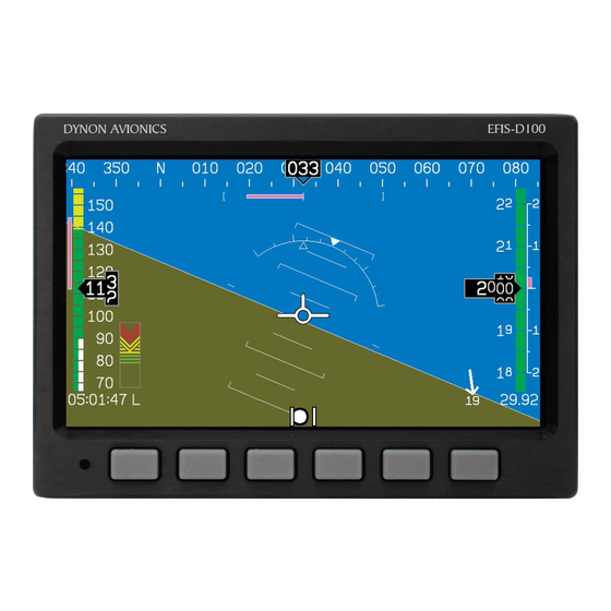
EFIS-D100 Pilot’s User Guide. Description The EFIS-D100 uses solid-state sensor technology to give an accurate and easy-to-understand display. To ensure accuracy in its readings, it is very important that you install the instrument correctly and perform the specified calibration steps. This installation guide will help you through that process. -
Page 9: Wiring
Power is fed to the EFIS-D100 via pins in the female DB25 connector as shown on the 25-Pin Female EFIS Harness diagram on page 2-2 The EFIS-D100 system-wide power requirement is 12 watts typical and 17 watts maximum. -
Page 10: 25-Pin Female Efis Harness
Wiring 25-Pin Female EFIS Harness Below is the wiring diagram of the EFIS 25-pin female harness. If you purchased your harness from Dynon Avionics, it is color coded according to the chart on the following page. EFIS-D100 Installation Guide... - Page 11 DSAB-B Page 3-9 No Connect No Connect No Connect White (bundled) PC Serial Ground Page 3-4 EFIS-D100 Transmit / PC Serial Page 3-4 White (bundled) Receive (RS-232) White/Orange (Red on some Page 3-1 EDC-D10A Data B harnesses) White/Blue (Black on some...
-
Page 12: Wiring System Overview
The following block diagram depicts the basic layout of the EFIS electrical connections and is for reference only. Read the specific instructions for each connection prior to installation. The colors shown refer to the Dynon-supplied EFIS harness. EFIS-D100 Installation Guide... -
Page 13: Instrument Installation
(away from magnetic interference) such that its pitch is as close to that of the EFIS-D100 as possible. It does not need to be directly along any axis of the EFIS- D100. It should be mounted with the long... -
Page 14: Edc-D10A Communication Cable
EDC-D10A connected to it. Observe the displayed heading and then hold one of the earpieces of a headset near the front of the EFIS-D100. If the EDC-D10A is correctly wired, you should see no change in the displayed heading when the headset earpiece and its magnetic... -
Page 15: Power Inputs
Instrument Installation speaker is near the EFIS-D100. If you see a substantial change in heading, there is a communication problem between the EFIS-D100 and the EDC-D10A. The metal shield around the EDC communication cable is connected to the short black/white wire emanating from the DB25. -
Page 16: Serial Communication Cable
If you do not have a serial port on your PC, use the included USB-to-Serial adapter to connect the EFIS-D100 to your PC’s USB port. Ensure that the adapter driver CD is inserted in your PC before plugging the adapter into the USB port for the first time. Also, do not have your EFIS- D100 plugged into the USB-to-Serial while installing the driver. -
Page 17: Sl30 And/Or Gps Connection
EFIS-D100 (e.g., pin 9 on the DB25). When a Dynon product is connected to a GPS, it will synchronize its Zulu clock to the time output by the GPS. -
Page 18: If You Own Only A Flightdek-D180
White There are four different serial formats used by transponders. The EFIS-D100 can output any of these formats. To select which format the EFIS- D100 sends out its serial encoder output port, you must choose the appropriate format via the menu system. -
Page 19: Serial Altitude Formats
ALT 05200[CR] Example message Format 4 Trimble, Garmin GTX327 (set on Icarus input), Garmin Used By GTX330 (set on Icarus input), Icarus 9600 Baud rate ALT, space, five altitude bytes, carriage return Format ALT 05200[CR] Example message EFIS-D100 Installation Guide... -
Page 20: Audio Alert Output
Outside terminal To ground To set the volume of the AOA alarm, you will need your EFIS-D100 powered on and the alarm output wired as described above. Enter the EFIS menu by pressing any button (except the leftmost or rightmost) beneath an EFIS page. Press MORE > SETUP > MORE > MORE >... -
Page 21: Dynon Smart Avionics Bus (Dsab) Wiring
The EFIS-D10A, EMS-D10, DSAB-B Blue EFIS-D100, EMS-D120, and FlightDEK-D180 products all have the hardware to support DSAB connections; currently the only supported function is transmitting data from an EMS product to an EFIS product. Once you connect your EFIS product and EMS product via the DSAB lines, you will have access to EMS pages on your EFIS. -
Page 22: Panel Location And Mounting
Avoid placing the instrument near heater vents or any source of extremely hot or cold air. Keep in mind that the air surrounding the EFIS-D100 during operation may be no warmer than 50 °C. Plan a panel location that allows convenient viewing of the instrument with no obstruction. -
Page 23: Connecting Static & Pitot Lines
If you purchased Dynon’s AOA pitot tube, note that it has pitot and AOA ports on it, but not static. You will need to provide your own source of static pressure for the EFIS-D100 and any other instrument in your panel which requires it. -
Page 25: Efis Calibration And Configuration
This section will take you through a series of steps to make sure that you have properly installed and configured your EFIS-D100. As in the User’s Guide, the term, “button #1” refers to the leftmost button on the front panel of the EFIS-D100, “button #2,” the next button to the right, and so on. -
Page 26: Edc-D10A Heading Calibration (On Ground Only)
EFIS-D100 (i.e., you see the heading tape displayed on the EFIS main page), and have located a suitable place to perform the calibration, perform the following steps: 1. Turn on the EFIS-D100 and allow it to warm up for at least 15 minutes before performing the calibration. - Page 27 15 second timer. Let the time run out before proceeding. 11. Press the END button. This will cause the EFIS-D100 to pause as it calculates. This pause should last between 1-20 seconds. However, if the collected data is poor, this can take as long as 5 minutes.
-
Page 28: Configure Airspeed Color Thresholds
When you have completed all 5 settings, you have completed the airspeed color thresholds configuration. Note that you will not be able to see some of the colors until the aircraft has achieved airspeeds in the range of each threshold. EFIS-D100 Installation Guide... -
Page 29: Appendix
5. APPENDIX The appendices contain additional information pertaining to the installation and maintenance of the EFIS-D100 You will find here a table of weights, specifications, a configuration table, the maintenance manual, the OAT Installation and Operating Guide, the AOA Pitot Installation Guide, and the Blind encoder Serial-to-Parallel Installation Guide. -
Page 30: Firmware Upgrade
MORE > DIM and increase the brightness until it will not increase anymore. 4. Let the unit remain on for 2 hours. 5. If, after these 2 hours, your EFIS-D100 has not turned off and does not display the INTERNAL BATTERY LOW warning, your battery passes the capacity test. - Page 31 EDC-D10A is failed has been disconnected. If you wiring or connectors. Examine the have an OAT connected to wiring run between the EFIS-D100 your EDC-D10A, you will and EDC-D10A for possible lose this reading, as well. problems.
-
Page 32: Troubleshooting Guide
Appendix TROUBLESHOOTING GUIDE The following table provides a list of potential issues that the EFIS-D100 may experience. The symptom is given on the left side while the probable solution is listed at the right. Problem Solution After performing a magnetic Orient your plane in a known direction, preferably on a calibration the EFIS-D100’s... -
Page 33: Instructions For Return
Dynon representative, the issue cannot be resolved, we will provide you with an RMA number to use when shipping the EFIS-D100 to us. If your unit is still under warranty, the repairs will be performed and the EFIS-D100 will be returned promptly. If your warranty has expired, the Dynon representative will make arrangements with you and make you fully aware of the costs before proceeding with the repair. -
Page 34: Appendix B: Dynon Oat Probe Installation And Usage
The following instructions provide information on installing and using the EFIS-D100 OAT probe. Keep in mind that this probe is designed specifically to work with the EFIS-D100. Do not expect it to work properly with another OAT or TAS/Density Altitude system. If you own an Dynon EMS product with an OAT installed, your EFIS-D100 can receive its OAT value from the EMS via the DSAB wires. -
Page 35: Oat/Tas/Da Display
To connect the blue wire, white wire, and shield (the three ground connections) into one pin, crimp a connector onto the stripped end of the ground wires from the EFIS-D100 (or, if using the Dynon-supplied harness, use the existing pinned ground lead). Strip some extra insulation off this ground wire. -
Page 36: Calibration And Adjustment
Ensure that you have selected the number corresponding to your OAT in the OAT INSTALLED menu as described above. It can sometimes take as long as 5 seconds for the EFIS-D100 to lock onto the OAT reading. Ensure that all wiring is correct and that there are no shorted or open connections. -
Page 37: Appendix C: Dynon Aoa/Pitot Installation And Calibration Guide
TOOLS AND MATERIALS REQUIRED • Dynon Avionics AOA/Pitot probe. • Two plumbing lines (usually ¼” soft aluminum or plastic tubing) routed from the EFIS-D100 to the probe mounting location. • Adapters to interface with the 3/16” aluminum tubing from the probe to whatever plumbing lines are installed in the airplane (AN 919-2D for 3/16 to ¼... -
Page 38: Dimensions
Appendix DIMENSIONS Standard mount Boom mount 5-10 EFIS-D100 Installation Guide... -
Page 39: Installation
3/16 plumbing lines from the probe to whatever plumbing lines run back to the EFIS-D100 in your aircraft (AN 919-2D for 3/16 to ¼). We strongly recommend using aircraft grade fittings such as standard AN fittings. Make sure the plumbing lines will not chafe or interfere with any aircraft control systems. -
Page 40: Alarm Setup
FINISH. At this point, the angle-of-attack has been calibrated. If it is not visible, make it visible through the menu system (see “Show/hide display items” in EFIS-D100 Pilot’s User Guide). This calibration should result in the lowest angle-of-attack stall occurring just above the red/yellow boundary. -
Page 41: Appendix D: Encoder Serial-To-Gray Code Converter Installation
EFIS-D100 and outputs standard Mode-C parallel Gray code into your Mode-C transponder. This Encoder Converter requires data from the EFIS-D100 and is not to be confused with other standalone encoders available on the market. While the installation is not complex, it is important that you install the unit correctly. -
Page 42: Step 2: Connecting To The Efis-D100
Ground, which are green (or red) and black respectively, and 2 feet in length. Connect these wires to the EFIS-D100 25-pin female harness. Ensure that your EFIS-D100 is powered off. Then connect the black EFIS Ground wire to pin 21. Then, connect the green wire to pin 13 (Serial Encoder Transmit) on the EFIS harness. -
Page 43: Step 3: Efis-D100 Encoder Format
Black Serial Encoder Ground STEP 3: EFIS-D100 ENCODER FORMAT For proper communication the EFIS Altitude Encoder format must be set to format number one. To change this setting, from the main menu, select: MORE > SETUP > MORE > ALTENC. -
Page 44: Appendix E: Replacing The Efis-D100 Battery Pack
D100. Remove the battery door. Do not remove any other screws from the back of the unit. (If you previously had a battery) Disconnect the battery from the EFIS-D100 by unplugging the battery connector and gently pull out old battery (it is o.k. to gently pull on the battery wire to get the battery out). -
Page 45: Appendix G: Efis-D100 Specifications
Appendix Appendix G: EFIS-D100 Specifications 6.95” wide x 4.90” tall x 4.51” deep (177 x 125 x 115 mm) Mechanical Operating -22° to 122° F (-30° to 50° C) Temperature Voltage: 10 - 30 Vdc Power Power: 12 watts typical; 17 watts maximum...
Need help?
Do you have a question about the EFIS-D100 and is the answer not in the manual?
Questions and answers