Dynon Avionics EFIS-D100 Pilot's User Manual
Electronic flight information system
Hide thumbs
Also See for EFIS-D100:
- Installation manual (104 pages) ,
- User manual (89 pages) ,
- Installation manual (41 pages)
Table of Contents
Advertisement
Quick Links
Advertisement
Table of Contents

Related Manuals for Dynon Avionics EFIS-D100


Summary of Contents for Dynon Avionics EFIS-D100
- Page 1 EFIS-D100 Electronic Flight Information System Pilot’s User Guide Revision B For use with firmware version 1.08 10/27/2006 Dynon Avionics This product is intended for the experimental aircraft category and is not approved for installation in certified aircraft...
-
Page 3: Copyright
Visit the Dynon Avionics website (www.DynonAvionics.com) for current updates and supplemental information concerning the use and operation of this and other Dynon Avionics products. EFIS-D100 Pilot’s User Guide... -
Page 5: Limited Warranty
These instruments are intended for experimental aircraft only at this time. Dynon Avionics makes no claim as to the suitability of its products in connection with FAR 91.205 For warranty information please contact: Dynon Avionics, Inc. 19825 141 Place NE Woodinville, WA 98072 PH: (425) 402-0433 FAX: (425) 984-1751 EFIS-D100 Pilot’s User Guide... -
Page 7: Table Of Contents
About this Manual ................................1-2 2. Product Overview EFIS-D100 Hardware ................................2-1 Sensors and Inputs ..............................2-1 Outputs ..................................2-1 Buttons..................................2-1 Display..................................2-2 Power..................................2-2 3. Product Operation Front Panel Layout ................................3-1 Display....................................3-2 Screens and Pages..............................3-2 Cycling Between Screens ............................3-4 Menus ....................................3-6 Page-Sensitive Menus..............................3-6 EFIS-D100 Pilot’s User Guide... - Page 8 Set the clock................................5-6 Change clock format..............................5-7 Show/hide display items ............................5-7 Check firmware version............................5-8 INFO – Informational Items ............................. 5-9 DIM – Changing screen brightness..........................5-11 TIMER – Setting and using a timer ..........................5-12 viii EFIS-D100 Pilot’s User Guide...
- Page 9 Multiple Alarms.................................7-2 8. Appendix Appendix A: Serial Data Output............................8-2 EFIS Serial Data Output ............................8-2 Appendix B: PC Support Program ............................8-4 Appendix C: Troubleshooting ............................8-4 Unit Errors .................................8-4 Alert Messages ................................8-5 Firmware Version Display............................8-8 Appendix D: EFIS-D100 Specifications..........................8-9 EFIS-D100 Pilot’s User Guide...
-
Page 11: Introduction Welcome
When connected to a Dynon EMS-D10/D120 series system the EFIS-D100 can retrieve and display EMS information at the push of a button. The EFIS-D100 is also capable of displaying HSI information, provided it is properly connected to a Garmin SL30 or a compatible GPS device. -
Page 12: About This Manual
Introduction About this Manual This guide serves two purposes. The first is to help you configure and get acquainted with the EFIS-D100’s many functions. The second is to give you quick access to vital information. In the electronic (.PDF) version of this manual, items in the Table of Contents and cross-references act as hyperlinks taking you to the relevant section in the manual that the word refers to. -
Page 13: Product Overview
HSI information is obtained from a Garmin SL30 or a compatible GPS unit through a unidirectional serial port. OUTPUTS The EFIS-D100 has an output to drive an external audible warning device (not supplied) to alert the pilot whenever attitude, timer, AOA (if installed) or other alarms occur. -
Page 14: Display
The display is a 7-inch, 854 by 480 pixel, 400 or 800 nit LCD screen, depending on the model. POWER The instrument requires 10 to 30 volts DC for operation. The internal battery is an optional accessory to the EFIS-D100, allowing the unit to operate in the event of an external power failure. •... -
Page 15: Product Operation
EFIS Operation section. Front Panel Layout All normal operation of the EFIS-D100 happens via the front panel. The front panel contains buttons and a display. • Buttons – There are six buttons on the front panel of the EFIS-D100. These buttons are numbered one through six, with button one being the leftmost and button six being the rightmost. - Page 16 Product Operation Display The EFIS-D100 display is the most obvious and commonly used output of the device. It is capable of displaying EFIS, HSI, and/or engine data simultaneously. SCREENS AND PAGES The terms in the following bulleted list are used in this section and are defined as follows: •...
- Page 17 The SCREEN LIST Menu uses icons to illustrate the layout for each screen configuration. EFIS/EMS EFIS/AUX EFIS/FUEL EFIS/TIMES EMS/EFIS EMS/AUX EMS/TIMES EMS/FUEL EFIS (default EFIS-D100 boot-up screen; in default rotation) EFIS/EMS EFIS/HSI (in default screen rotation) EMS/HSI EFIS-D100 Pilot’s User Guide...
-
Page 18: Cycling Between Screens
If you various screen configurations. wish to access screens that are not in your rotation, use the SCREEN LIST as described above. EFIS-D100 Pilot’s User Guide... - Page 19 Press SETUP, then press ORDER to display the menu used to change the screen order. Scroll through the pre-defined screens using the DOWN▼/UP▲ buttons. Press the MV DN▼ EFIS-D100 Pilot’s User Guide...
-
Page 20: Menus
Likewise, press the MV UP▲ button to move the selected screen up in the screen list. Menus All interaction with the EFIS-D100 is accomplished through the use of its menu system. The menu system is accessed and navigated via the six buttons located on the front of the unit. -
Page 21: Flow
Upon exiting the menu, the screen returns to its normal appearance. Any given EFIS-D100 menu describes the functionality of the buttons below it. The label located directly above the button denotes its current function (e.g., pushing button two in the menu in the figure below will invoke the BARO command). - Page 22 EXIT button. In any menu with more options than will fit on a line, the This varies based upon how deep you are into the MORE button displays the rest of the menu. menu system. EFIS-D100 Pilot’s User Guide...
- Page 23 Note: EMS-based pages use data that is obtained from Dynon’s EMS products. You may only display these pages on your EFIS-D100 if you own a Dynon EMS-based product, and the two units are connected. Refer to the EFIS- D100 Installation Manual for details regarding proper connection between Dynon products and other devices in your system.
-
Page 24: Efis Main Pages
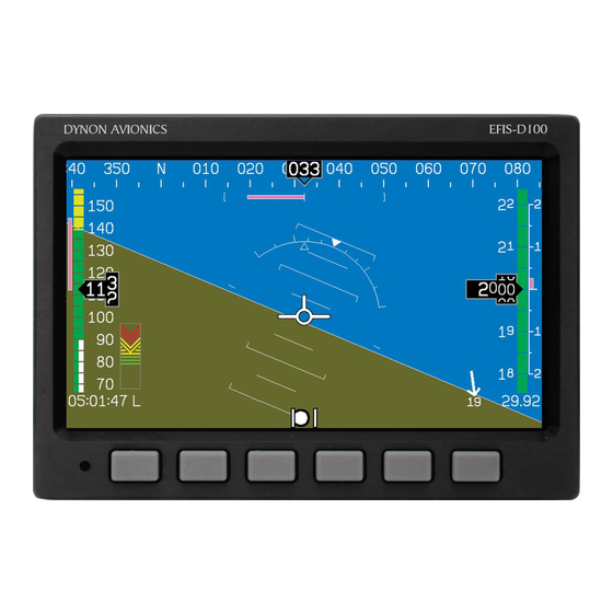
EFIS MAIN PAGES Available in 1/3, 2/3 and full formats The EFIS-D100 default screen rotation includes a full screen EFIS page. The EFIS page is also available in 2/3 and 1/3 screen formats. In these configurations, it is paired with HSI or EMS pages. - Page 25 During the first 30 seconds of operation, the altitude tape and digital readout are not displayed as the unit needs a small amount of time before altitude measurements are deemed accurate. Altitude units are EFIS-D100 Pilot’s User Guide...
- Page 26 The airspeed tape utilizes 4 colors to give you a graphical representation of your speed. By default all of the color thresholds are set at 0, displaying a grey tape. You must set the values of the airspeed color thresholds via the SETUP menu. Please see the EFIS-D100 Installation Guide for more information on setting the airspeed color thresholds.
- Page 27 The current barometer setting is displayed at the bottom right of the screen below the altitude tape. This shows the value that you have entered for the barometer when setting your elevation. The value is shown in either inches of Mercury or millibars depending on your preference set in the BARO menu. EFIS-D100 Pilot’s User Guide...
-
Page 28: Hsi Page
HSI PAGE Available in 1/3 format Your EFIS-D100 can function as a Horizontal Situation Indicator (HSI) when it is receiving input from either an external GPS or Garmin SL30 nav/comm. The HSI information is overlaid on a directional gyro (DG) representation of the EFIS's stabilized magnetic heading information. -
Page 29: Times Page
EFIS Times EMS Times the EFIS-D100 unless a Dynon EMS product is properly connected and running. The tach timer keeps track of engine time (normalized to the user- configured cruise RPM). The Hobbs timer records the duration of time engine oil pressure is at 15 PSI or higher. -
Page 30: Lists Pages
(14 lines by 40 characters). Checklists must be defined and uploaded to the EFIS-D100 as described by the Dynon Product Support Program. Reference the help file that accompanies this software for more information. To download the Dynon Product Support Program, visit www.dynonavionics.com/downloads. -
Page 31: Efis Operation
POWER – Power on/off When the EFIS-D100 is turned off but still has a power source via one of the three power inputs, press the far left button to turn the unit on. Likewise, once the unit is on and no menus are displayed, push and hold the leftmost button to turn it off. -
Page 32: Bugs - Setting Bug Markers
As you increment or decrement the heading bug value it will rollover at 360 degrees, returning the value to 0. If you have the bug toggled on, you will see the arrow move left or right across the heading tape as you decrement or increment its value. EFIS-D100 Pilot’s User Guide... -
Page 33: Airspeed
Set Value dialog box is displayed in the lower center of the display. Press SEL to select which digit to change and buttons 4 (DEC) and 5 (INC) to decrease and increase each digit’s value respectively. Press the SYNC button to synchronize the altitude bug to your current altitude. EFIS-D100 Pilot’s User Guide... -
Page 34: Lists - Using Checklists And Data Panels
MISC. To load checklists and data panels onto your EFIS-D100, you must upload them as described in the help file that comes with the Dynon Product Support Program. Pushing the LIST button will display the 5 main categories as set up in the Dynon Support Program. -
Page 35: Setup - Setting Preferences
To accommodate this fact, you may “zero” the currently displayed pitch of the EFIS-D100. The best way to do this is to adjust the displayed pitch once you are flying straight and level and can observe that a non-zero pitch is achieved. -
Page 36: Set The Clock
(and, if necessary for the time zone, the half-hour offset) for the local time. Be aware that connecting to the EFIS-D100 with the Dynon Product Support Program will reset the time;... -
Page 37: Change Clock Format
TURNRT (turn rate indicator), and AOABAR (angle of attack tape). Pressing button 5, corresponding to MORE, will display a third menu of items that can be toggled on and off. These are CLOCK (clock and time zone EFIS-D100 Pilot’s User Guide... -
Page 38: Check Firmware Version
The firmware version submenu gives you two important pieces of information: the version of EFIS-D100 firmware that your unit is currently running and the number of hours the EFIS-D100 has been on. From the second line (press MORE) of the SETUP submenu, press the VRSION button; this brings up the firmware version submenu. This submenu will also display the number of hours of on-time the unit has had. -
Page 39: Info - Informational Items
EFIS-D100. The bottom row, labeled MN, is the minimum g-force experienced by the EFIS- D100 since reset. This last value can be viewed as the maximum negative g-force experienced by the EFIS-D100. EFIS-D100 Pilot’s User Guide... - Page 40 If you are losing altitude, a down arrow is displayed to the right of the vertical sp value. The units of VSI are feet/minute. OAT (Outside Air Temperature) EFIS-D100 supports two different t ypes of OATs Installed Sensor...
-
Page 41: Dim - Changing Screen Brightness
Pressing DRKR will decrease screen brightness until it reaches its minimum. It is not possible to turn the screen completely black via this menu. Note that if power to the EFIS-D100 is cycled, the screen will be restored to full brightness. -
Page 42: Timer - Setting And Using A Timer
SEC until the seconds digits increment to the desired value. • You may not have an up timer and a down timer running at the same time. 5-12 EFIS-D100 Pilot’s User Guide... -
Page 43: Oatset - Setting Temperature Offset
If you did not purchase an EFIS or EMS outside air temperature sensor from Dynon Avionics, you may still manually adjust the OAT to an approximate value. With this manually entered information, the EFIS-D100 can calculate and display true airspeed (TAS) and density altitude as it does when an OAT is connected. Ensure that you have indicated that an EFIS OAT is not installed;... -
Page 45: Hsi Operation Required Connections
30 NAV/COMM radio via a serial connection (NAV data), a Garmin GNS-430/530 GPS/NAV/COMM (GPS data), or any GPS that outputs in either NMEA-0183 or aviation format. Please refer to the EFIS-D100 Installation Guide for instructions on how to connect these devices to your Dynon network. Also ensure your GPS device is configured to output magnetic headings since all calculations and displays are done in reference to the local magnetic heading. - Page 46 180 degrees and will indicate properly with no reversal needed. If you put the SL 30 into back course mode, you need to set the course to the heading of the back course runway, not the primary ILS runway, or the CDI needle will be reversed. EFIS-D100 Pilot’s User Guide...
- Page 47 2. Digital heading indicator. The number in this box is the current magnetic heading of the aircraft in degrees from 001 to 360. The accuracy of this data depends on the accuracy of the heading calibration for your EFIS-D100. 3. Directional Gyro (DG). The ring of tick marks and numbers acts as a traditional directional gyro.
-
Page 48: Navigation Overlay
Each dot indicates two degrees of deviation from the radial that has been chosen as the course. When tuned to a localizer, each dot represents 0.5 degrees of deviation. When on course, the course indicator and the CDI make a solid line, EFIS-D100 Pilot’s User Guide... - Page 49 These elements will only appear when the active and/or standby are tuned to an active frequency. A digital display of these bearings and a reminder of which symbol represents each bearing is in the text area of the page. EFIS-D100 Pilot’s User Guide...
-
Page 50: Gps Overlay
CDI needle on an HSI rotates with the DG and course indicator. By turning the aircraft towards the CDI needle so the CDI needle is "on top" of the course line you will reduce your deviation. EFIS-D100 Pilot’s User Guide... -
Page 51: Hsi Menu Structure
BUG - This is the same as going into BUGS > HDG in the main EFIS menu. This menu allows you to adjust and toggle a heading bug that appears on the DG display as well as the EFIS heading tape. EFIS-D100 Pilot’s User Guide... - Page 52 COURSE (Nav mode, Localizer active) - This is used to set the OBS/course. The SL-30 does not allow you adjust the OBS when tuned to a localizer so this must be done locally on the instrument. • SCALE (GPS mode) - This is used to toggle through the three GPS scale modes. EFIS-D100 Pilot’s User Guide...
-
Page 53: Alarms Alarm Indicators
Note that alarms may not be acknowledged during the initial two seconds of the first alarm. In an alarm condition, the EFIS-D100 does not alert you audibly. The audio out connection on the EFIS-D100 is for AOA alerts only. If you have a Dynon EMS-based product installed, connected to both your EFIS-D100 and cockpit audio system, EMS-based alarms will still sound an audible alarm. -
Page 54: Alarm Acknowledgement
3. The ACK button displays a number indicating the number of stacked up alarms. 4. When the last alarm is acknowledged, the Alarm Bar and Alarm Menu are removed from the screen. 5. Once the top alarm is acknowledged, the next alarm in the stack is shown. EFIS-D100 Pilot’s User Guide... -
Page 55: Appendix
This appendix contains information not covered in the main section of the manual. This section contains reference tools such as a detailed description of the serial data format output by the EFIS-D100, a specifications sheet, and a troubleshooting guide. This section also contains details regarding EFIS-D100 servicing. -
Page 56: Appendix A: Serial Data Output
Each of these serial ports outputs data for its respective instrument function. Technical information on the installation and connection to these serial ports can be found in the EFIS-D100 Installation Guide. To log both EFIS and EMS data, you must connect both serial ports to a PC. This serial data can be logged using any standard serial terminal program such as HyperTerminal®. - Page 57 An internal-use status bitmask containing 24 bits. Bit 0 (LSbit) is 0 when the altitude field is displayed altitude, 1 when pressure altitude. Internal use Internal use - ignore Checksum The ascii-hex 2 byte sum of all 49 preceding bytes CR/LF Carriage Return, Linefeed = 0x0D, 0x0A EFIS-D100 Pilot’s User Guide...
-
Page 58: Appendix B: Pc Support Program
Navigate to the Heading Adjustment menu by pressing SETUP > MORE > MAGADJ. Increment or decrement the value of the heading until the EFIS-D100 heading corresponds to the direction in which your plane is pointed. EFIS-D100 Pilot’s User Guide... -
Page 59: Alert Messages
RESET DFLTS. ALERT MESSAGES The following table describes the error/warning messages that the EFIS-D100 could display. The meaning of the message is given here as well as information about when the error message conditions will go away. - Page 60 Pressing any button will remove the text of the INDETERMINATE a rate faster than 150 degrees/second. Rotating the alert. However, the horizon indication will remain unit faster than this threshold will saturate the grey/black until the unit has resumed normal EFIS-D100 Pilot’s User Guide...
- Page 61 If this is the case, try uploading the new firmware again with the EDC- D10A connected. Attempt the connection within the first few seconds of operation. Note that the EFIS-D100 does not have internal magnetic sensors and thus requires the EDC-D10A be connected. TIMER EXPIRE...
-
Page 62: Firmware Version Display
FIRMWARE VERSION DISPLAY The firmware version submenu gives you two important pieces of information: the version of EFIS-D100 firmware that your unit is currently running and the number of hours the EFIS-D100 has been on. To display this information, activate the either the EMS or EFIS Main Page menu then press MORE > SETUP >... -
Page 63: Appendix D: Efis-D100 Specifications
Appendix Appendix D: EFIS-D100 Specifications Mounting: 6.95” wide x 4.90” tall x 4.51” deep (177 x 125 x 115 mm) Weight: 2 lb. 6 oz. (1.08 kg) Mechanical 3 lb. (1.36 kg) with internal battery -22° to 122° F (-30° to 50° C) - Page 64 Appendix 1 - Audio Alarm 1 - RS-232 bidirectional PC communication Inputs/Outputs 1 - RS-232 data input (GPS, SL30, etc.) 1 - Dynon Smart Avionics Bus (DSAB) 8-10 EFIS-D100 Pilot’s User Guide...
Need help?
Do you have a question about the EFIS-D100 and is the answer not in the manual?
Questions and answers