Table of Contents
Advertisement
Quick Links
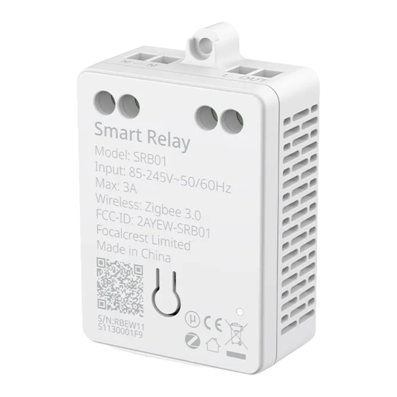
Product Introduction
Smart Relay uses Zigbee wireless technology and can be used in different loads, including incandescent lamps,
halogen lamps, LED lamps and fluorescent lamps. It could be installed near the light or light fixture itself. This
In-Wall Relay Switch
device is compatible with standard Zigbee 3.0 gateway or devices for remote control and inter-operation.
Smart Switch Sub-Assembly is an optional component of the In-Wall Relay Switch. The Smart Switch
(Zigbee)
Sub-Assembly is designed to allow mechanical switch to work with switch commands from the network. For
example, after turning off the lights with a mechanical switch, you can turn on the lights through network
Instruction Manual
commands.
One Smart Relay can be connected to one or a series Smart Switch Sub-Assemblies (Multiple-point control).
Rev. 051723 v1.0
P/N SRB01 SS01
One Smart Switch Sub-Assembly can be connected to two circuits of loads, each of which must use one
Smart Relay.
Complete Accessories Include
Model
Input Voltage
Max. Load Power
Smart Switch
Min. Load Power
Smart Relay
Sub-Assembly
Applicable to
Operating Temperature
Operating Humidity
Switch Wire
Product Size (L*W*H)
Wireless Connectivity
Wireless Profile
Instruction
Double Sided Foam Pad
Manual
RF Characteristics
Fixing Screw
Instruction Manual
Setup Code
RESET
button
Installation Instructions
Caution: Read this manual before attempting to install the device! Using this
product in a manner other than intended voids your warranty. Further, EVVR
ApS is NOT liable for any damage incurred with the misuse of this product.
Caution: All installations of this device should be performed by a qualified or
licensed electrician!
Caution: Metal casings, mirrors, electrical appliances, etc.,
may affect, reduce, or interfere with wireless communication.
Caution: Use this product in an indoor environment.
TECHNICAL SPECIFICATIONS
SRB01/SRB01A
SS01
AC 85V~245V
AC 85V~245V
AC 110V/300W
AC 110V/300W (2-gang in total)
AC 220V/600W
AC 220V/600W
No limit
No limit
Light Fixtures
Toggle, Momentary Switch
0~40°C (32°~104°F)
0~40°C (32°~104°F)
5~85% RH
5~85% RH
59.4mm * 39.3mm * 21.2mm
33.5mm * 28.2mm * 17.3mm
(2.34in. x 1.55in. x 0.83in.)
(1.32in. x 1.11in. x 0.68in.)
Zigbee 2.4GHz IEEE 802.15.4
Zigbee 3.0
Operating frequency: 2.4GHz
Range:
30m~60m
Internal antenna
Fixing hole
L
Power input for
Fastening
live wire
screws
N
OUT
Neutral wire
Output for
Indicator
load
light
Caution: Product must be installed on a 10A line.
1
Turn off the power
Warning: Turn OFF electrical power from the breaker box
or electrical service panel before installing or servicing this
product. Improper use or installation can cause SERIOUS
INJURY, DEATH, or LOSS/DAMAGE OF PROPERTY.
2
Connect the Smart Relay to the load
It is recommended to install Smart Relay
near the lamp.
3
Connect the Smart Switch Sub-Assembly to the traditional switch
With Smart Switch Sub-Assembly you can control Smart Relay using traditional switch.
Smart Switch Sub-Assembly is compatible with 1/2 gang switch, and two Smart Switch
Sub-Assemblies can be installed to support 3/4 gang switch.
NOTE:
'SW1' controls the 'L1'
'SW2' controls the 'L2'
4
Overall diagram
Fastening screws
If the Smart Switch Sub-Assembly and Smart Relay are connected correctly, it should look like one of the diagrams below.
SW1: External switch control for load
SW2: External switch control for load
Wiring a Single Light Switch
Switch connection port
L
L : Power input for live wire
N
L1: Power output for live wire
L2: Power output for live wire
Wire connection port
Note: When Smart Switch Sub-Assembly is connected to a 1-gang switch, the switch must be connected to SW1 external switch jack (not SW2).
Please choose one of the installation methods to connect the N line according to your actual installation environment.
You can choose one of the two diagrams below to connect the wires according to your
installation environment.
L
N
N
OUT
NOTES FOR THE DIAGRAM:
N - neutral wire
L - live wire
L
N
L
L OUT
SW1
LOAD
L
N
N
OUT
LOAD
LOAD
OUT - output live wire
Note:
One end of the Switch Wire should
be inserted into the "SW1" and "SW2"
jacks on the Smart Switch
Sub-Assembly and the other end
can only be connected to a
traditional switch. Do not connect
the wire to the live, neutral, or load
wires, or else it will damage the
device.
SW1
SW2
Note:
The black wires of the Switch Wire
must connect to the common
terminal of the traditional switch.
L
L OUT
N
SW1
LOAD
Advertisement
Table of Contents

Related Manuals for EVVR SRB01


Summary of Contents for EVVR SRB01
- Page 1 Caution: Read this manual before attempting to install the device! Using this Caution: Product must be installed on a 10A line. product in a manner other than intended voids your warranty. Further, EVVR ApS is NOT liable for any damage incurred with the misuse of this product.
- Page 2 Peel off the paper from the adhesive and affix the Smart Switch Sub-Assembly to the recommended radiator and your body. support@evvr.io indicate a successful operation. location on the box. This transmitter must not be co-located or operating in conjunction with any other antenna or transmitter. Rev. 051723 v1.0 P/N SRB01 SS01...
Need help?
Do you have a question about the SRB01 and is the answer not in the manual?
Questions and answers