Advertisement
Quick Links
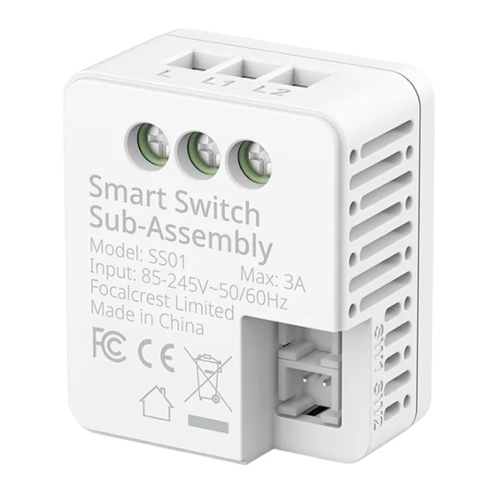
In-Wall Relay Switch
Smart Switch Sub-Assembly
Instruction Manual
Rev. A-032021
*Please see separate Smart Relay manual for
complete instructions. The Smart Switch
Sub-Assembly is an accessory part of In-wall
Relay
Switch
and
only
functional
connected with the Smart Relay.
Complete Accessories Include
Instruction
Manual
Smart Switch ×1
Instruction Manual ×1
Panel Connector Wire ×2
Product Introduction
Smart Switch Sub-Assembly is an optional compo-
nent of the In-Wall Relay Switch when they are used
together. The Smart Switch Sub-Assembly is
designed to allow mechanical switch panels to work
with switch commands from the network. For
example, after turning off the lights with a mechani-
cal switch panel, you can turn on the lights through
network commands.
One Smart Relay can be connected to one or a series
Smart Switch Sub-Assembly (multiple point control).
One Smart Switch Sub-Assembly can be connected
to two circuits of loads, each of which must use one
Smart Relay.
TECHNICAL SPECIFICATIONS
Model number
SS01
Input Voltage
AC 85V~245V
AC 110V/300W
Max. Load Power
AC 220V/600W
Min. Load Power
No limit
Supported Switch Type Toggle, Momentary
0~40°C
Operating Temperature
(32°~104°F)
P/N SS01
Relative Humidity
5~85% RH
33.5mm * 28.2mm * 17.3mm
Product Size (L*W*H)
(1.32in. x 1.11in. x 0.68in.)
when
NOTE:
Fastening screws
SW1: External switch control for load
SW2: External switch control for load
Panel Connection port
L : Power input for live wire
L1: Power output for live wire
L2: Power output for live wire
Wire Connection port
Installation Instructions
Caution: Read this manual before attempting to
install the device! Using this product in a manner
other than intended voids your warranty. Further, Evvr
is NOT liable for any damage incurred with the misuse
of this product.
Caution: All installations of this device should be
performed by a qualified or licensed electrician!
Caution: Product must be installed on a 10A line.
Warning: Turn OFF electrical power from the breaker
box or electrical service panel before installing or
servicing this product. Improper use or installation
can cause SERIOUS INJURY, DEATH, or LOSS/DAM-
AGE OF PROPERTY.
Caution: Use this product in an indoor environment.
1
Connect the wires to the switch panel
With Smart Switch Sub-Assembly you can control Smart
Relay using traditional switch panel.
'SW1' controls the 'L1'
'SW2' controls the 'L2'
Smart Switch Sub-Assembly compatible with 1/2 gang
switch panel, and two Smart Switch Sub-Assemblies can
be installed to support 3/4 gang switch panel.
The diagram to the right shows the connection of wires.
2
Overall Diagram
If the Smart Switch Sub-Assembly and Smart Relay are connected correctly, it should look like diagram
below. For more instructions on how to install the Smart Relay, please see the Smart Relay Manual.
Wiring a Single Light Switch
L
N
SW1
In a single switch environment, please choose one of the installation methods to install on the L1
line according to your actual installation environment.
SW1
L
N
L
L OUT
LOAD
SW2
L
L OUT
N
SW1
LOAD
Advertisement

Related Manuals for EVVR SS01


Summary of Contents for EVVR SS01
- Page 1 Wiring a Single Light Switch install the device! Using this product in a manner Product Introduction other than intended voids your warranty. Further, Evvr is NOT liable for any damage incurred with the misuse Smart Switch Sub-Assembly is an optional compo- of this product.
- Page 2 The device will leave the current network and re-enter pairing mode. At the same time the indicator light will slowly flash blue and wait until pairing is successful or timeout. Please contact us for any technical issue support@evvr.io Rev. A-032021 P/N SS01...
Need help?
Do you have a question about the SS01 and is the answer not in the manual?
Questions and answers