Advertisement
Quick Links
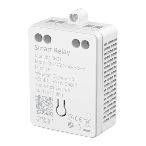
In-Wall Relay Switch
Smart Relay (Zigbee version)
Instruction Manual
Rev. B-092822
*Please see separate Smart Switch Sub-Assembly
manual for complete instructions.
Complete Accessories Include
Double Sided Foam
Smart Relay
1
×
Pad
1
×
Instruction
Manual
Fixing Screw
1
×
Instruction Manual
Device Identification QR Code (Zigbee)
Product Introduction
Smart Relay uses Zigbee wireless technology
and may be used in different loads, including
incandescent lamps, halogen lamps, LED lamps
and fluorescent lamps. It is small in size and may
be installed in the box of light fixtures. This device
is compatible with standard Zigbee 3.0 gateway
or devices for remote control and inter-operation.
P/N SRB01
Technical Specifications
Model
SRB01
Input Voltage
AC 85V~245V
AC 110V/300W
Max. Load Power
AC 220V/600W
Min. Load Power
No limit
Type of Load
Lighting
0~40°C
Operating Temperature
(32°~104°F)
Operating Humidity
5~85% RH
Wireless Connectivity
Zigbee 2.4GHz IEEE 802.15.4
Zigbee Profile
Zigbee 3.0
Operating frequency: 2.4GHz
Range: 30m~60m
RF Characteristics
Internal antenna
59.4mm * 39.3mm * 21.2mm
Product Size (L*W*H)
(2.34in. x 1.55in. x 0.83in.)
Fastening screws
1
×
RESET Button
N
Power input for
Neutral wire
Installation Instructions
Caution: Read this manual before attempting to install the device! Using this product in a manner other than
intended voids your warranty. Further, Evvr ApS is NOT liable for any damage incurred with the misuse of this
product.
Caution: All installations of this device should be performed by a qualified or licensed electrician!
Caution: Product must be installed on a 10A line.
Caution: Metal casings, mirrors, electrical appliances, etc., may affect, reduce, or interfere with wireless
communication.
Warning: Turn OFF electrical power from the breaker box or
electrical service panel before installing or servicing this
product. Improper use or installation can cause SERIOUS
INJURY, DEATH, or LOSS/DAMAGE OF PROPERTY.
1
Connect wires per wiring diagram as follows
Caution: If you have purchased a Smart Switch Sub-Assembly
to use with it, please follow the installation instructions on the
Smart Switch Sub-Assembly manual.
With Smart Relay, you can turn a traditional lamp into a Zigbee
smart lamp. It is recommended to install Smart Relay near the
lamp.
You can choose one of the two diagrams below to connect the
wires according to your installation environment.
L
N
Fixing hole
NOTES FOR THE DIAGRAM:
N - neutral wire
Indicator Light
2
Fix Smart Relay on a flat, cleaned surface
Stick the foam pad at the recommended position on the Smart
L
Power input for
Relay and then place the relay on a flat, cleaned surface.
live wire
Turn ON electrical power and check if the wires are connected
correctly. If they are correct, the indicator light will be on when the
load light, the light(s) connected to the switch, is on.
OUT
Output for load
L
N
N
L OUT 1
LOAD
L - live wire
L OUT - output live wire
Caution:
Use this product in
an indoor
environment.
L OUT
LOAD
Recommended
placement
Advertisement

Related Manuals for EVVR SRB01


Summary of Contents for EVVR SRB01
- Page 1 Caution: Read this manual before attempting to install the device! Using this product in a manner other than Smart Relay uses Zigbee wireless technology intended voids your warranty. Further, Evvr ApS is NOT liable for any damage incurred with the misuse of this and may be used in different loads, including product.
- Page 2 The separate collection and recycling FCC ID: 2A68U-SRB01 of your waste equipment at the time of disposal will help to conserve natural resources and ensure that it is recycled in a manner that protects human health and the environment.
Need help?
Do you have a question about the SRB01 and is the answer not in the manual?
Questions and answers