Table of Contents
Advertisement
Advertisement
Table of Contents

Related Manuals for ray FACE

Summary of Contents for ray FACE
- Page 1 RAYFace 3D Scanner Model: RFS200 User Manual RUG-3623-EN Rev. 1.0...
- Page 2 The operator must follow instructions and safety regulations described in the user manual to prevent any injury to the operator and damage to the product. Copyright Ray Co., Ltd. Publication number: RUG-3623-EN_Rev.1.0 (Revised Sep. 01, 2022) This manual is subject to quality upgrade and specification change without prior notice.
-
Page 3: Table Of Contents
RAYFace Contents Contents User Manual Introduction ................6 Related Terms ......................6 Symbols ........................6 Safety Information ...................... 7 System Symbols ......................7 Precautions for Installation ..................8 Precautions for Use ....................9 Precautions for Power Connection ................9 Precautions for Cleaning the Product ............... 11 Label ........................ - Page 4 RAYFace Contents Software Installation ....................28 RAYFace Screen Composition.................. 30 Register Scanner ...................... 31 Server Registration ....................34 RAYScan Server Registration ................34 RAYFace Server Registration ................37 Linked Program Registration ..................39 Operating Software..................42 Register Subject ....................... 42 Capture ........................
- Page 5 RAYFace 1. Introduction Introduction...
-
Page 6: User Manual Introduction
RAYFace 1. Introduction User Manual Introduction The following user manual contains not only a specific step-by-step guide on how to use RAYFace (referred to as “the product”), but also the basic information regarding the product. Please keep this manual for future reference. Please read the safety regulations before using the product. -
Page 7: Safety Information
RAYFace 1. Introduction Safety Information The following safety information must be read and understood before using the product. Please check the safety precautions to use it safely and correctly. Improper use of the product may cause bodily injury or death. The owner of the product must ensure that all precautions, safety measures and maintenance procedures are performed. -
Page 8: Precautions For Installation
Do not install in a place where there is a strong light directly to the front of the product. ▪ ▪ Do not install in a place where there is a strong light directly to the subject's face or background. ▪... -
Page 9: Precautions For Use
RAYFace 1. Introduction ▪ Install it 10cm away from the end of the table. Leaving a BATTERY in an extremely high temperature surrounding environment can result in an EXPLOSION or the leakage of flammable liquid or gas. A BATTERY subjected to extremely low air pressure that may result in an explosion or the leakage of flammable liquid or gas. - Page 10 RAYFace 1. Introduction ▪ Do not place objects (chemicals, water containers, and little metallic objects such as tweezers) near the product. ▪ Remove the power cord if the product emits strange sound, smell, or smoke and contact the seller. ▪ Use with a rated voltage.
-
Page 11: Precautions For Cleaning The Product
RAYFace 1. Introduction Precautions for Cleaning the Product Risk of electric shock or fire ▪ Remove the power cord when cleaning the product. ▪ Use soft, lint-free cloth when cleaning. Soak it with a little bit of water to clean the product, and be careful not to get water on the inside. - Page 12 RAYFace 2. Product Introduction Product Introduction...
-
Page 13: Product Introduction
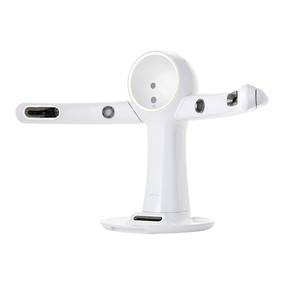
Product Introduction Usage RAYFace is a scanner that uses the onboard cameras to scan images of the subject’s face in all directions simultaneously and reconstruct the scanned data to create a 3D model. The 3D face data obtained from RAYFace is used for various modeling tasks. -
Page 14: Sections And Functions (Scanner Body)
Projector to project a Scan Pattern. DLP Projector Face Cam Camera to scan an image from the front. LED lighting for a subject’s left side of the face. Left Light LED lighting for a subject’s right side of the face. Right Light LED lighting for a subject’s lower side of the face. -
Page 15: Sections And Functions (Calibration Kit)
Sections and Functions (Calibration Kit) [Front] [Side] [Rear] Item Description Face Cam Cal Pattern Panel that calibrates the cameras, front and rear panels are used for calibration. Teeth Cam Cal Pattern Terminal to connect to RAYFace main body. Main Body Port... - Page 16 RAYFace 3. Installation Installation...
-
Page 17: Installation
RAYFace 3. Installation Installation Installation Environment Installation Setting The product should be installed on a level surface within 1° of inclination and on a table capable of stably supporting a weight of 44 lb(20 kg) or more and an area of 20 in x 20 in(50 cm x 50 cm) or larger. -
Page 18: Working Environment
RAYFace 3. Installation Working Environment Do not install the product in a place exposed to direct sunlight or ultraviolet (UV) light. Use the product at room temperature between 10°C to 35°C / 50°F to 95°F. Do not install near a wireless apparatus or mobile device that generates electromagnetic interference. -
Page 19: System Requirements
RAYFace 3. Installation System Requirements Desktop Item Minimum Requirements Recommended Requirments Intel Core i5-10600 Intel Core i7-10700 32GB 16GB NVIDIA GeForce RTX 3070 8GB NVIDIA GeForce RTX 2060 6GB 1TB SSD Storage 1TB SSD 1920 X 1080 1920 X 1080 Monitor 1 x USB port 2.0 1 x USB port 2.0... -
Page 20: Maintenance
RAYFace 3. Installation Maintenance As described in the description, the user must conduct periodic maintenance. It is the user’s responsibility to maintain the product in order to prevent potential problems. Maintenance Period Description After initial installation, proceed with calibration by using the provided Initial Installation calibration kit. -
Page 21: Product Installation
RAYFace 3. Installation Product Installation Fix both left and right arms of main body Take out the main body from the packaging, place it on the table, rotate the arm, and prepare as shown in the figure below. While pulling each plunger handle, rotate the left and right arms slowly. When you hear a click, the arms are locked horizontally. -
Page 22: Connect Power
RAYFace 3. Installation Connect Power For the initial installation, make sure that the power outlet conforms to the AC adapter specifications. Connect the power cord and AC adapter, as shown in the following figure. Please contact your local distributor if the product and the enclosed power cord are different from those used in your region. -
Page 23: Power On And Off
RAYFace 3. Installation Power On and Off Press and hold the main power switch for 2 seconds to power up. Press and hold the main power switch for 4 seconds to power down. Connect to Network Connect the RAYFace to a computer (or network) using a network cable, as shown in the following figure. -
Page 24: Network Setting Configuration
RAYFace 3. Installation Network Setting Configuration RAYFace provides various network environments, as shown in the following figures. Direct connection between computer and RAYFace. When connecting the computer and RAYFace directly, set a static IP addresss on the computer. The IP address applied to the computer should be set differently from RAYFace. -
Page 25: Connect To Pc
RAYFace 3. Installation Connect to PC IP information can be modified by connecting RAYFace to a PC using a USB cable as shown in the figure below. The USB cable only needs to be connected for modifying IP information. -
Page 26: Assemble Calibration Kit
RAYFace 3. Installation Assemble Calibration Kit Assemble the calibration kit by using the included screws and screwdriver. -
Page 27: Proceed With Calibration
RAYFace 3. Installation Proceed with Calibration After placing the assembled Calibration Kit in front of the RAYFace, insert it into the front of the base and align it in the correct position. Make sure to insert the calibration base correctly until the printed side is not visible. -
Page 28: Software Installation
RAYFace 3. Installation Software Installation You can download the RAYFace installation software by accessing https://www.rayteams.com/. Refer to the guide as shown below to complete the installation. Figure Description Install the RAYFace software by running the installation file. At this time, a warning window will pop up asking if the user continues the installation on the user administration account. - Page 29 RAYFace 3. Installation Once the initial set up for the installation has been completed. Click [Install] button to continue the installation process. Wait until the RAYFace installation has been completed. Click [Finish] button to close the setup page. RAYFace icon is created on the desktop.
-
Page 30: Rayface Screen Composition
RAYFace 3. Installation RAYFace Screen Composition Item Description Menu Subject list, acquisition, settings, etc. can be set. Subject list Subject list can be viewed and managed. Image list Subject's scanned images are shown. -
Page 31: Register Scanner
RAYFace 3. Installation Register Scanner Figure Description Connect RAYFace and PC with the provided USB cable. Execute the software and click [ ] button. Go to [Device] tab. Click [+] button and [Add device] window will pop up. - Page 32 RAYFace 3. Installation In the [Add device] window, select the COM port connected to the scanner and click the [Connect] button. If your PC has multiple COM ports, click the [Search] button to find the COM port connected to the scanner. If there is no COM port connected to the PC, the message will be displayed.
- Page 33 RAYFace 3. Installation [Connect] button will load scanner information. Modifying the network settings and clicking the [Save] button saves the network settings to the scanner and registers the scanner to the PC. In case of updating the scanner’s firmware, you can update the firmware after registering the scanner.
-
Page 34: Server Registration
RAYFace 3. Installation Server Registration RAYScan Server Registration When using RAYScan CBCT, the user can register the server in order to import the CT data and Object Scan data and merge them with Smile Scan data. Figure Description Start the Program and press [ ] button. - Page 35 RAYFace 3. Installation Once the RAYScan server IP address has been entered, click on [Verify] button to confirm if the server is able to connect. When RAYScan server is able to connect with the inserted information, the pop up window as shown on the left will appear.
- Page 36 RAYFace 3. Installation When correct address RAYScan server has been entered and [Save] button has been pressed, the RAYScan server IP address will be stored.
-
Page 37: Rayface Server Registration
Any 3D facial scan data captured by RAYFace can be shared with the other PCs connected to the same network. The PC where the RAYFace device is connected and 3D face scanning occurs is hereafter defined as the RAYFace server. Any PC on the same network where the device is not connected and 3D face scanning does not take place is defined as RAYFace client. - Page 38 RAYFace 3. Installation Figure Description Enter the RAYFace server IP address, and press [Add] button. entered RAYFace server cannot be connected, the pop up window as shown on the left will appear. Once the RAYFace server connects, it will be added to server list connection status icon will...
-
Page 39: Linked Program Registration
RAYFace 3. Installation Linked Program Registration 3rd party software can be linked to transmit data from RAYFace. Figure Description Start the program and press the[ button. . Move to [Link] menu. For Exocad integration, set the path for [DentalDB] [DentalCADApp]. Once the path has been designated, RAYFace utilizes the DentalDB to create a case and save data. - Page 40 RAYFace 3. Installation Assign the path for Dolphin. Once the path has been assigned, the user can start Dolphin with the data created under RAYFace.
- Page 41 RAYFace 4. Operating Software Operating Software...
-
Page 42: Operating Software
RAYFace 4. Operating Software Operating Software Register Subject A user can register subjects. Figure Description Clcik [ ] button to enter the subject registration screen. Enter ID, name, DOB (Date of Birth), gender and click [OK] button. Refer to ‘4.4.1.2 Name Format’ for details about capture options. -
Page 43: Capture
RAYFace 4. Operating Software Capture You can capture a subject and set up the options. Capture Figure Description Select a subject to capture and click [ button. Preparing the capture. When the scanner is ready, the lights will be turned on and live view is displayed. Adjust the subject’s position. - Page 44 RAYFace 4. Operating Software Capture until the subject’s natural expression is captured. After clicking the [ ] button, the scanner captures and transfers the date to the PC. The capture lists and transfer status are displayed at the bottom. When you select a capture list, the selected capture data is displayed.
- Page 45 RAYFace 4. Operating Software Upon completion of capture, click [ ] button to return to the list of subjects.
-
Page 46: Capture Options
RAYFace 4. Operating Software Capture Options Adjust White Balance Figure Description You can adjust the color temperature of photos under [White balance] option. As the color temperature decreases, the photo turns bluish. If the ambient light uses a red color, lowering the color temperature can neutralize the ambient light color. - Page 47 RAYFace 4. Operating Software Adjust Brightness Figure Description You can adjust the brightness of the scanner’s light under [Brightness] option. Adjust the brightness based on the ambient light.
- Page 48 RAYFace 4. Operating Software Horizontal Flip (Live View) Figure Description Under [Horizontal flip] option, you can flip the live view horizontally. The camera position does not change even if it is flipped left to right. On the left, images captured from the left camera are displayed and the same on the right camera.
- Page 49 RAYFace 4. Operating Software Bookmark Figure Description Among the scan data, you can bookmark scanned photos. Bookmarks also displayed in the subject list and if a photo is bookmarked, it cannot be deleted. You can bookmark a photo in both the scan list and 3D view.
-
Page 50: Captured Data Management
RAYFace 4. Operating Software Captured Data Management A user can validate, export and delete the subject’s captured data. Validate Captured Data Figure Description Select a subject to display the related data. Captured data is grouped by date. Click a date to shrink or expand the data display. - Page 51 RAYFace 4. Operating Software In the first column, specify the period to retrieve the scan data. In the second column, specify the condition of the scan data. In the third column, specify the scan type of data. In the fourth column, specify the bookmark condition.
-
Page 52: Unreconstructed Data Management
RAYFace 4. Operating Software Unreconstructed Data Management Figure Description Select a unreconstructed-capture data and click [ ] button to initiate 3D reconstruction. Unreconstructed data is permanently deleted after a certain period of time. Refer to ‘4.4.1.1 General Settings’ for details about capture options. - Page 53 RAYFace 4. Operating Software Deleted data can be permanently deleted or restored from recycle bin. When all the data of the subject is permanently deleted, the subject is also deleted. Refer to ‘4.3.7 Deleted Data Management’ for details about capture options. Double-clicking on the unreconstructed data allows one to view the captured data.
-
Page 54: Reconstructed Data Management
RAYFace 4. Operating Software Reconstructed Data Management Figure Description Double-click on a reconstructed data to display the 3D reconstructed data. 3D reconstructed data is displayed. Click [ ] button to delete captured data. Deleted data can be permanently deleted or restored from recycle bin. - Page 55 RAYFace 4. Operating Software If there is a problem with the 3D reconstructed data, open the image and check the subject's posture and position. adjust overall size transperency of the acquisition window, and hide and show the positioning guide. You can check the image by zooming in/out by using the [Mouse Scroll Wheel] and move the image by dragging it while holding the [Left Mouse Button].
- Page 56 RAYFace 4. Operating Software If you do 3D reconstruction again, the current data is deleted and reconstructed again. Clicking [OK] repeats the reconstruction. If you feel that the screen is narrow, you can expand it by hiding the subject list, or clicking the [ ] button to switch to full screen.
- Page 57 RAYFace 4. Operating Software You can save the reconstructed image by clicking the [ ] button. You can enter data alignment menu by clicking the [ ] button.
-
Page 58: Move Captured Data
RAYFace 4. Operating Software Move Captured Data Figure Description If you select the wrong subject, you can move the scan data to another subject. Select the scan data that you want to move and click the [ ] button. Select the subject for whom you want to move the scan data to. -
Page 59: Export Captured Data
RAYFace 4. Operating Software Export Captured Data Figure Description Select the data that you want to export and click the [ ] button. Specify the path to save the data and name the data. You can select only the data you want to save by using the checkbox next to each data. - Page 60 RAYFace 4. Operating Software Korean, Chinese, Japanese, etc., you may not be able to open it in an external CAD program. If you export to use in an external CAD program, make sure to specify its file name in English. RFS file stands for RAYFace project file.
-
Page 61: Import Captured Data
RAYFace 4. Operating Software Import Captured Data Figure Description You can import an exported RFS file in the [Import RFS files] menu. If you select the RFS file, it check the scan data included in the RFS file. Selecting [OK] imports the scan data. Retrieve the name and ID of the subject from the captured data and register the subject in the list. - Page 62 RAYFace 4. Operating Software If a subject with the same ID but a different name is imported, the ID of the subject will be changed during the process. The ID can be automatically generated or entered manually. You can import captured data from another computer in the [Import captured data].
- Page 63 RAYFace 4. Operating Software In order to import captured data, alll files are required in the original save path. In the original save path, the pre-reconstructed data (captured data) and post-reconstructed data exist. In order to access the original save path, select the subject and click [Open captured data folder].
-
Page 64: Deleted Data Management
RAYFace 4. Operating Software Deleted Data Management Figure Description Click [ ] button to move to the recycle bin. A list of the subjects with deleted data is displayed and the deleted data of the subject is displayed. For deleted data, the remaining period until permanent deletion is displayed. - Page 65 RAYFace 4. Operating Software Select the deleted data and click [ ] button to restore the data. Click [OK] button to proceed with restoring the selected data. Click [ ] button to restore all deleted data of the subject. Click [OK] button to proceed with restoration of all deleted data.
-
Page 66: Settings
RAYFace 4. Operating Software Settings A user can change various settings of RAYFace, IP address, update firmware. General Settings Set the language, name format, data retention time, data path and import captured data. Figure Description Run the RAYFace software and click [ button. - Page 67 RAYFace 4. Operating Software General Settings Figure Description Go to [Language] and select your preference in the list. Confirmation window is displayed for the change. Click [OK] and the RAYFace will restart automatically. Go to [Date Format] and select your preference in the list.
- Page 68 RAYFace 4. Operating Software You can specify from 14 to 60 days (Default: 30 days). If the check box is left unchecked, any unreconstructed data will not be deleted. Go to [Reconstructed data retention time] and set the retention period of data that has been reconstructed into a 3D model among the captured data.
- Page 69 RAYFace 4. Operating Software You can set indoor light frequency in [Indoor Light Frequency] option. When RAYFace is installed, it is automatically set between 50Hz and 60Hz according to the country setting of the operating system. If the operating system's country setting is different from the actual one, you have to set it according to the country’s mains power supply specifications.
- Page 70 RAYFace 4. Operating Software Name Format Figure Description Go to [Name Format] and select your preference in the list. [Full] option allows to enter full name of a subject. [FirstMiddleLast] [LastFirstMiddle] [LastMiddle First] option allows the user to enter subject’s name in a specified brackets.
- Page 71 RAYFace 4. Operating Software If the First, Middle and Last name are entered separately, the name is displayed according to the current language setting. If you change the name format, the display changes according to the changed format. If you change the name format to [Full], the display changes according to the format at the time of entering a name.
- Page 72 RAYFace 4. Operating Software Captured Data Path Figure Description [Captured data path] option allows the user to change the data save path for RAYFace server and client sync data. Changing the path only affects the local PC where this option has been utlized, this does not affect the data save path for other synced PCs in the network.
- Page 73 RAYFace 4. Operating Software [Archive path] option allows the user to change the data save path for the data which only resides in RAYFace server as an archival data and are not synced. Changing the path only affects the local PC where this option has been utlized, this does not affect the data save path for other synced PCs in the network.
-
Page 74: Device Settings
RAYFace 4. Operating Software Device Settings A user can change the scanner’s IP address and update the firmware. Figure Description Run the RAYFace software and click [ button. Go to [Device] tab. - Page 75 RAYFace 4. Operating Software IP Address Settings Figure Description Connect RAYFace and computer with provided USB cable. Select the COM port and click [Connect] button. Click [Search] buttton to find the COM port if the computer has multiple COM ports. If there is no COM port connected to the computer, this message will appear.
- Page 76 RAYFace 4. Operating Software If the selected COM port is not connected to RAYFace, this message will appear. Click [Connect] button to load the scanner information. Modify the network settings and click [Save] button to save the network settings.
- Page 77 RAYFace 4. Operating Software Firmware Update Figure Description Click [Firmware Update] button. Select the firmware file of RAYFace. If the selected file is not the firmware file of RAYFace, this message will appear. If the selected file does not support the version of RAYFace, this message will appear.
- Page 78 RAYFace 4. Operating Software Calibration Figure Description Go to [Calibration] menu. After installing the calibration target, connect the USB A type port on the back of the scanner body and the USB B type port on the calibration kit. Click [Start] button, calibration will start. When calibration target scanning is finished, calibration is automatically calculated.
- Page 79 RAYFace 5. Status Indicator Status Indicator...
-
Page 80: Status Indicator
RAYFace 5. Status Indicator Status Indicator RAYFace Indication Figure Description LED status indicator is located at the front mirror of RAYFace. [Yellow] It indicates the booting state. [Blue] It indicates that the scanner is ready to shoot, after the booting completes. [Red] Please restart RAYFace, there is a connection error with the device. -
Page 81: Appendix A. Product Specifications
RAYFace Appendix A. Product Specifications Appendix A. Product Specifications Item Description Dimension (W x H x D) 808 x 390 x 552 mm / 31.8 x 15.3 x 21.7 in. Weight 9.5 kg / 20.9 lbs Connectivity Ethernet , USB White LED CCT 5700 K Input: 100-240V~, 50/60Hz, 1.5A... -
Page 82: Appendix B. Messages
RAYFace Appendix B. Messages Appendix B. Messages Message Cause Guide Currently installed A camera that is not Contact your sales representative to cameras contain supplied replace the camera. unsupported firmware. manufacturer is installed. Open the back cover and confirm that cable related cables are connected properly. - Page 83 RAYFace Appendix B. Messages Message Cause Guide If captured data cannot be found or if the subject was properly captured and the Unable to reconstruct The scanned data has scanned data has been corrupted. the captured data in 3D been corrupted. This data cannot be recovered.
- Page 84 RAYFace Appendix B. Messages Message Cause Guide Retry to update the firmware. Wrong update file has There is a problem with If the same error message appears, been loaded. the firmware binary file. download the firmware binary file again. A problem occurred Restart the device.
- Page 85 RAYFace Appendix B. Messages Message Cause Guide The IP address and gateway must be on Gateway is not on the The gateway is not on the same network defined by the same network with the the same network as the netmask.
- Page 86 RAYFace Appendix B. Messages Message Cause Guide There is a problem with Update the scanner firmware. A problem occurred scanner board If the problem persists even after the during serial installed firmware update, contact your sales communication. RAYFace. representative. There is a problem with Update the scanner firmware.
- Page 87 RAYFace Appendix B. Messages Message Cause Guide The path in which the current captured path where data is saved cannot be designated as a This path cannot be set current captured data is new path. to save captured data. saved is seleted as the new save path.
- Page 88 RAYFace Appendix B. Messages Message Cause Guide Please confirm whether the calibration kit has been connected to the device properly, calibration kit has been attached properly, Calibration scan inspect if there are any damages to the image is not sufficient for calibration kit, see if the target pattern on the the calibration or the Calibration failed.
- Page 89 RAYFace Appendix B. Messages Message Cause Guide Please confirm if the correct IP address for Could not connect to the the RAYScan server has been entered, Unable to connect to RAYScan server IP as and confirm RAYScan server is operating the RAYScan server.
-
Page 90: Appendix C. Regulations
RAYFace Appendix C. Regulations Appendix C. Regulations Product Disposal (Refer to wastes collection systems by countries) This symbol on the product, component to document, indicates that it should not be disposed of with other household wastes when disposing of the product. Please cooperate to promote the continuous recycling of resources by separating and recycling the product from others to avoid environmental harm and check the terms of the purchase agreement. - Page 91 Ray Co., Ltd. All rights reserved.
Need help?
Do you have a question about the FACE and is the answer not in the manual?
Questions and answers