Table of Contents
Advertisement
Quick Links
Advertisement
Table of Contents

Related Manuals for Dräger PAS MAC1000


Summary of Contents for Dräger PAS MAC1000
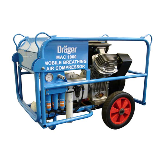
- Page 1 MOBILE BREATHING-AIR COMPRESSOR PAS MAC1000 OPERATOR’S HANDBOOK Draeger Safety UK Ltd Ullwater Close, Kitty Brewster Industrial Estate, Blyth, Northumberland, NE24 4RG, UK Tel N : +44 (0) 1670 352891 Fax N : +44 (0) 1670 356266 E‐mail: marketing@draeger.ltd.uk Website:...
-
Page 2: Table Of Contents
CONTENTS Page INTRODUCTION GENERAL ARRANGEMENT PAS:MAC1000 On Site Compressor Breathing-Air Components TECHNICAL DATA Compressor OPERATING INSTRUCTIONS Safety Precautions Siting Pre-operation Checks Starting Instructions Stopping Instructions SERVICE Before Working on the Compressor Preventive Maintenance Schedule for the Compressor BA Filtration Unloader Check Valve SPARES Standard Components Service Spares... -
Page 3: Introduction
INTRODUCTION The PAS:MAC 1000 portable compressor set is designed to deliver breathing quality air suitable for one man wearing air-fed respiratory protective equipment. A 230V/1.5kW electric motor driving a ‘V’ configuration twin cylinder, reciprocating compressor, provides air which, after processing, is purified to breathing quality conforming to EN 12021 (within certain environmental limitations). -
Page 4: Compressor
ATLAS COPCO LE15-10-S COMPRESSOR BREATHING-AIR COMPONENTS 1 Outlet pressure gauge 2 Breathing-air outlet coupling 3 Pre-filter 4 Main coalescing oil removal filter 5 Activated carbon filter 6 Membrane dryer 7 Lockable outlet pressure regulator TECHNICAL DATA PAS:MAC 1000 - 2 -... -
Page 5: Compressor
COMPRESSOR The compressor is a lubricated, twin cylinder, single stage reciprocating unit; air is drawn through an air filter mounted in between the cylinders. After compression the air passes through an unloader/check valve, an aftercooler and finally a pulsation vessel mounted under the unit before passing through a set of filters to provide air of breathable quality. -
Page 6: Operating Instructions
OPERATING INSTRUCTIONS SAFETY PRECAUTIONS In addition to normal safety rules which should be observed with stationary air compressors and equipment, the following safety directions and precautions are of special importance. When operating this unit, the operator must employ safe working practices and observe all related local work safety requirements and ordinances. -
Page 7: Starting Instructions
Electrical cable visually inspect cable and plug for damage. Statutory insulation inspections may be required – see local rules. Note: Electric cable and plug can be stowed within the tool box. Ensure cable is run through the cut-out in the front of the box when in use. -
Page 8: Service
SERVICE BEFORE WORKING ON THE COMPRESSOR Potentially lethal voltages are used to power this machine. Disconnect power lead from mains supply prior to carrying out any service work. Do not undertake any work until the compressor and pulsation vessel have been relieved of all pressure. Wait until the compressor’s vent down cycle is complete. -
Page 9: Ba Filtration
BREATHING-AIR FILTRATION Item Description Part N Service Interval Pre-filter element FIL 0471 2000 hours/12 months Main coalescing filter element FIL 0473 2000 hours/12 months Activated carbon filter element FIL 0475 1000 hours/ 6months PAS:MAC 1000 - 7 - OCTOBER 2010... -
Page 10: Unloader Check Valve
UNLOADER CHECK VALVE OPERATION The Mark II maintains air vessel pressure levels between a “cut- out” pressure level and a “cut-in” pressure level. The difference between the two is known as the “differential”. The Mark II senses air pressure through a small orifice in the side of the OUT port of the valve. - Page 11 REGULATOR ADJUSTMENT Cut-out pressures are adjustable from 60 psi to 250 psi with the standard silver spring. The differential (difference between cut-out and cut-in pressures) is typically set at the factory at about 15% of the cut-out pressure. This is usually a suitable differential and will not normally need to be readjusted.
-
Page 12: Spares
SPARES STANDARD COMPONENTS Description Factair Part N Compressor and motor assembly COM 0186 Pressure control device VAL 0169 Aftercooler cooling tubes COO 0082 Pressure relief valve 12 bar VAL 0178 Pulsation vessel FAB 0154 Pre-filter complete FIL 0470 Main coalescing filter complete FIL 0472 Activated carbon filter complete FIL 0474... -
Page 13: Drawings
DRAWINGS GA DRAWING PAS:MAC 1000 - 11 - OCTOBER 2010... -
Page 14: Pneumatic Circuit
PNEUMATIC CIRCUIT PAS:MAC 1000 - 12 - OCTOBER 2010... -
Page 15: Electrical Circuit
ELECTRIC CIRCUIT PAS:MAC 1000 - 13 - OCTOBER 2010... -
Page 16: Certificate Of Conformity
CERTIFICATE OF CONFORMITY DECLARATION OF CONFORMITY 73/23/EEC [known as ‘Low Voltage Equipment (LVD)’] 2006/42/EC [known as ‘Machinery Directive’] 2000/14/EC [known as ‘Noise Emission in the Environment Directive’ – Annex VIII]* *Notified body:- LRQA Ltd, Hiramford, Middlemarch Office Village, Siskin Drive, Coventry, CV3 4FJ Declare that under our sole Factair...
Need help?
Do you have a question about the PAS MAC1000 and is the answer not in the manual?
Questions and answers