LEAB MELFBOX User Manual
Electrical supply system for verhicles
Hide thumbs
Also See for MELFBOX:
- User manual (16 pages) ,
- Quick start manual (2 pages) ,
- User manual (12 pages)

Related Manuals for LEAB MELFBOX


Summary of Contents for LEAB MELFBOX
- Page 1 MELFBOX ELECTRICAL SUPPLY SYSTEM FOR VERHICLES USER MANUAL VERSION 2 06/01/2022 www.leab.eu LEAB Automotive GmbH Thorshammer 6 24866 Busdorf...
-
Page 2: Table Of Contents
Table of Contents LEAB Automotive GmbH Table of Contents 1 About this Manual................. 2 General Safety ..................2.1 Intended Use..................2.2 Foreseeable Misuse ................3 About this Product................. 4 Technical Specifications ................. 5 Creating a Body Cutout................6 Installation .................... -
Page 3: About This Manual
Qualified electricians. Any modifications to the product or its components are prohibited and do not conform to its intended use. Only use original LEAB or LEAB-approved accessories. Throughout the manual, you will be alerted to warnings and safety notices about potential hazards associated with handling the device. -
Page 4: General Safety
2 General Safety LEAB Automotive GmbH You will find useful tips and tricks in certain parts of the manual. These appear as follows: Tips provides additional, useful information. Read the tip carefully and follow the instructions where applicable. 2 General Safety This manual will help you to handle the system safely. -
Page 5: Intended Use
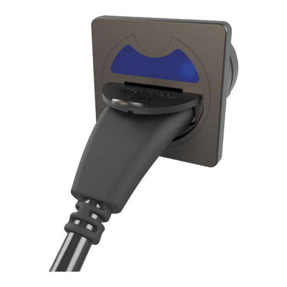
3 About this Product The MelfBox is a vehicle electrical supply system. It has a potential-free switching contact (normally open contact) to create an immobiliser. An electronic system prevents contact erosion. The operating display provides information about the current system status. -
Page 6: Technical Specifications
4 Technical Specifications LEAB Automotive GmbH 1 Cover 2 Housing with body seal 3 Housing seal 4 Cap 5 Retaining screw 4 Technical Specifications Part no. 1105002002 Modell MelfBox Nominal voltage (AC) 230 V (+/- 10%) Current, max. (AC) 16 A... -
Page 7: Creating A Body Cutout
2. Choose a site with minimum dust and which is protected from jet water. 3. Make sure that there is sufficient space at the assembly site. Fig. 2: MelfBox dimensions To create the body cutout, proceed as follows: 1. Saw a hole (Ø 55 mm) in the vehicle body. -
Page 8: Installation
ð The device is connected. Optional: Connecting the Immobiliser The MelfBox has a potential-free switching contact (normally open contact) to create an immobiliser. The design of the immobiliser depends on the vehicle. Inquire from your vehicle manufacturer. -
Page 9: Assembly
7 Assembly To install the device, proceed as follows: ü The cables in the MelfBox housing are correctly connected. ü The body seal is firmly seated on the housing. 1. Place the housing seal in the cap. -
Page 10: Operation
8 Operation Notice Inactive immobilisers can cause damage Note that immobiliser only works when the MelfBox is active (operating display illuminated). Electronics to prevent contact burnout requires voltage Contact N is electronically switched and is only open when a 230 V voltage is applied. -
Page 11: Operating Status
Yellow, steady light The MelfBox is active. No power is removed. – Check the connection of the consumers. – Check the fuse at the outlet of the MelfBox. NOTE! This operating status only occurs immediately after inserting the MelfBox coupling. The MelfBox does not switch back from “blue”... -
Page 12: Accessories
– Check the tightness of the supply unit in the vehicle body at regular intervals. 10 Accessories You can order accessories either through your dealer or directly from LEAB. Just visit our webshop at www.leab.eu or call us on: +49(0) 4621 9 78 60-110. Part number Description 1105001001 Connection cable 2.5 m... - Page 13 LEAB Automotive GmbH 12 EU Declaration of Conformity LEAB Automotive GmbH Thorshammer 6 24866 Busdorf...
- Page 14 12 EU Declaration of Conformity LEAB Automotive GmbH LEAB Automotive GmbH Thorshammer 6 24866 Busdorf...
- Page 15 LEAB Automotive GmbH 12 EU Declaration of Conformity LEAB Automotive GmbH Thorshammer 6 24866 Busdorf...
- Page 16 We make energy mobile. LEAB Automotive GmbH Thorshammer 6 DE-24866 Busdorf Tel: +49 (0) 4621 9 78 60-0 Fax: +49 (0) 4621 9 78 60-260 info@leab.eu It is prohibited to copy, duplicate, translate or otherwise pass on the content of this guide to third parties without the express written...
Need help?
Do you have a question about the MELFBOX and is the answer not in the manual?
Questions and answers