Advertisement

Quick Links

SERVICE
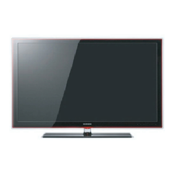
TFT-LED TV
UN32C5000QM / UN40C5000QM / UN46C5000QM
Refer to the service manual in the GSPN (see the rear cover) for the more information.
LED-TV
Chassis :
N98C
Model
:
UN32C5000QM
UN40C5000QM
UN46C5000QM
UN32C4000PM
Manual
1. Precautions
2. Product specifications
3. Disassembly and Reassembly
4. Troubleshooting
5. Exploded View & Part List
6. Wiring Diagram
Contents

Advertisement

Table of Contents
loading

Summary of Contents for Samsung UN32C5000QM

  • Page 1 1. Precautions 2. Product specifications 3. Disassembly and Reassembly 4. Troubleshooting 5. Exploded View & Part List 6. Wiring Diagram UN32C5000QM / UN40C5000QM / UN46C5000QM Refer to the service manual in the GSPN (see the rear cover) for the more information.
  • Page 2: Table Of Contents

    Contents 1. Precautions ......................1-1 1-1. Safety Precautions ......................1-1 1-2. Servicing Precautions ..................... 1-2 1-3. Electrostatically Sensitive Devices (ESD) Precautions ..........1-2 1-4. Installation Precautions ....................1-3 2. Product specifications .................... 2-1 2-1. Feature & Specifications ....................2-1 2-2. New Features explanation ....................2-7 2-3.
  • Page 3 Mideast & Africa http://mea.samsungportal.com © 2010 Samsung Electronics Co.,Ltd. This Service Manual is a property of Samsung Electronics Co.,Ltd. All rights reserved. Any unauthorized use of Manual can be punished under applicable Printed in Korea International and/or domestic law.
  • Page 4: Precautions

    1. Precautions 1. Precautions 1-1. Safety Precautions Follow these safety, servicing and ESD precautions to prevent damage and to protect against potential hazards such as electrical shock. 1-1-1. Warnings For continued safety, do not attempt to modify the circuit board. Disconnect the AC power and DC power jack before servicing.
  • Page 5: Servicing Precautions

    1. Precautions 1-2. Servicing Precautions WARNING: An electrolytic capacitor installed with the wrong polarity might explode. Caution: Before servicing units covered by this service manual, read and follow the Safety Precautions section of this manual. Note: If unforeseen circumstances create conflict between the following servicing precautions and any of the safety precautions, always follow the safety precautions.
  • Page 6: Installation Precautions

    1. Precautions 1-4. Installation Precautions For safety reasons, more than a people are required for carrying the product. Keep the power cord away from any heat emitting devices, as a melted covering may cause fire or electric shock. Do not place the product in areas with poor ventilation such as a bookshelf or closet. The increased internal temperature may cause fire.
  • Page 7: Product Specifications

    2. Product specifications 2. Product specifications 2-1. Feature & Specifications Model UN32C5000QM Feature Digital-TV, RF, 4-HDMI, 1-Component, 2-A/V, 2-USB, D-SUB ሪ Brightness : 450 cd/m2 ሪ Hgh Contrast Ratio : 50,000:1 ሪ Response Time : 4.5ms ሪ Specifications Item Description...
  • Page 8 2. Product specifications Model UN40C5000QM Feature Digital-TV, RF, 4-HDMI, 1-Component, 1-A/V, 2-USB2.0, D-SUB ሪ Brightness : 400 cd/m2 ሪ High Contrast Ratio : 50,000:1 ሪ Response Time : 4.5 ms ሪ Specifications Item Description LCD Panel 40inch FHD 60Hz Scanning Frequency Horizontal : 60 kHz ~ 73 kHz (Automatic) Vertical : 47 Hz ~ 63 Hz (Automatic) Display Colors...
  • Page 9 2. Product specifications Model UN46C5000QM Feature Digital-TV, RF, 2-HDMI, 1-Component, 1-A/V, 1-USB2.0, D-SUB ሪ Brightness : 400 cd/m2 ሪ High Contrast Ratio : 50,000:1 ሪ Response Time : 4.5ms ሪ Specifications Item Description LCD Panel 46inch FHD 60Hz Scanning Frequency Horizontal : 60 kHz ~ 73 kHz (Automatic) Vertical : 47 Hz ~ 63 Hz (Automatic) Display Colors...
  • Page 10 2. Product specifications Model UN32C4000PM Feature Digital-TV, RF, 2-HDMI, 1-Component, 1-A/V , 1-USB2.0, D-SUB ሪ Brightness : 300 cd/m ሪ High Contrast Ratio : 40,000:1 ሪ Response Time : 4.5ms ሪ Specifications Item Description LCD Panel TFT-LCD panel, RGB vertical stripe, SPVA mode, normaly black, 32-Inch viewable, 0.46125(H) ×...
  • Page 11 2. Product specifications CHANNEL FREQUENCY TABLE 1. OUTPUT FREQUENCY : ANALOG fv:45.75MHz, fs:41.25MHz DIGITAL Fc:44MHz 2. TUNING STEP SIZE : FIRST PLL 250KHz SECOND PLL 62.5KHz OSD CH NO CH NO CH NO CH NO Air-DTV Air-NTSC BAND Cable STD BAND Cable HRC Cable IRC 72.
  • Page 12 2. Product specifications OSD CH NO CH NO CH NO CH NO Air-DTV Air-NTSC BAND Cable STD BAND Cable HRC Cable IRC 499.25 ULTRA 498.00 499.25 505.25 ULTRA 504.00 505.25 511.25 ULTRA 510.00 511.25 517.25 ULTRA 516.00 517.25 523.25 ULTRA 522.00 523.25 529.25...
  • Page 13: New Features Explanation

    Anynet+ is a function that enables you to control all connected Samsung devices that support Anynet+ with your Samsung TV’s remote. The Anynet+ system can be used only with Samsung devices that have the Anynet+ feature. To be sure your Samsung device has this feature, check if there is an Anynet+ logo on it.
  • Page 14: Accessories

    Remark Remote Control & Batteries BN59-01020A (AAA x 2) Power Cord 3903-000532 32” BN63-06542A Cover-Bottom 40” BN63-06543A 46” BN63-06543A Samsung Electronics Service center 32” BN96-12930B Stand 40” BN96-12931B 46” BN96-12932B Screw 6003-000133 (for the stand - M4, L6) Owner’s Instructions...
  • Page 15: Disassembly And Reassembly

    3. Disassembly and Reassembly 3. Disassembly and Reassembly This section of the service manual describes the disassembly and reassembly procedures for the UN37C5000QM LCD TV. WARNING: This LED TV contains electrostatically sensitive devices. Use caution when handling these components. 3-1. Disassembly and Reassembly Cautions: 1.
  • Page 16 3. Disassembly and Reassembly Description Picture Description Screws 2. 32" C5000 : Remove the 15 screws of rear-cover. 40"/46" C5000 : Remove the 16 screws of rear-cover. 6003-000133 32" 6003-001003 40"_46" 3. Lift up the rear-cover. 4. Remove the speaker and Wooper.
  • Page 17 3. Disassembly and Reassembly Description Picture Description Screws 5. Lift up the stand link. Remove the 4 screws of bracket stand link. 6003-000133 6. Remove the 5 screws of main board and 5 screws of IP board. 6001-002283 6001-000115 7. Lift up the panel. Reassembly procedures are in the reverse order of disassembly procedures.
  • Page 18: Troubleshooting

    4. Troubleshooting 4. Troubleshooting 4-1. Troubleshooting 4-1-1. Previous check Check the various cable connections first. • Check to see if there is a burnt or damaged cable. • Check to see if there is a disconnected or loose cable connection. •...
  • Page 19 4. Troubleshooting 4-1-2. No Power The LEDs on the front panel do not work when connecting the power cord. Symptom The SMPS relay does not work when connecting the power cord. The units appears to be dead. The IP relay or the LEDs on the front panel does not work when connecting the power cord if the cables are improperly connected or the Main Board or SMPS is not functioning.
  • Page 20 4. Troubleshooting Location (Main) BOTTOM Detail A5V1 B13VS1 B5V1 A3.3V BD216 BD212 Pin #1~5 40" T-Con...
  • Page 21 4. Troubleshooting 4-1-3. No Video (Analog PC signal) Symptom Audio is normal but no picture is displayed on the screen. Check the PC source Major Check the Arsenal, Check the Chelsea. checkpoints This may happen when the LVDS cable connecting the Main Board and the Panel is disconnected. Power indicator LED is off.
  • Page 22 4. Troubleshooting Location (Main) BOTTOM Detail BD1104 BD1105 E_TXCLK- E_TXCLK+ BD1106 BD1107 O_TXCLK+ O_TXCLK- BD1108...
  • Page 23 4. Troubleshooting WAVEFORMS „ PC input (V-sink , H-sink , R/G/B) LVDS output...
  • Page 24 4. Troubleshooting 4-1-4. No video (HDMI1, 2 - Digital signal) Symptom Audio is normal but no picture is displayed on the screen. Check the HDMI source. Major Check the HDMI switch, Check the Chelsea. checkpoints This may happen when the LVDS cable connecting the Main Board and the Panel is disconnected. Power indicator LED is off.
  • Page 25 4. Troubleshooting Location (Main) BOTTOM Detail E_TXCLK- Pin #7 E_TXCLK+ O_TXCLK+ Pin #12 O_TXCLK-...
  • Page 26 4. Troubleshooting WAVEFORMS „ HDMI input (RX_Data, RX_Clk) LVDS output...
  • Page 27 4. Troubleshooting 4-1-5. No Video (Tuner_CVBS) Symptom Audio is normal but no picture is displayed on the screen. Check the Tuner CVBS source. Major Check the Tuner, Check the Chelsea. checkpoints This may happen when the LVDS cable connecting the Main Board and the Panel is disconnected. Power indicator LED is off.
  • Page 28 4. Troubleshooting Location (Main) BOTTOM Detail TP-VT E_TXCLK- E_TXCLK+ TP-B+_5V O_TXCLK+ O_TXCLK- 4-11...
  • Page 29 4. Troubleshooting WAVEFORMS „ LVDS output 4-12...
  • Page 30 4. Troubleshooting 4-1-6. No Video (Video CVBS) Symptom Audio is normal but no picture is displayed on the screen. Check the Video CVBS source Major Check the Chelsea. checkpoints This may happen when the LVDS cable connecting the Main Board and the Panel is disconnected. Power indicator LED is off.
  • Page 31 4. Troubleshooting Location (Main) BOTTOM Detail E_TXCLK- E_TXCLK+ TP-704 O_TXCLK+ O_TXCLK- 4-14...
  • Page 32 4. Troubleshooting WAVEFORMS „ CVBS OUT (Grey Bar) LVDS output 4-15...
  • Page 33 4. Troubleshooting 4-1-7. No Video (Component) Symptom Audio is normal but no picture is displayed on the screen. Check the Component source Major Check the chelsea. checkpoints This may happen when the LVDS cable connecting the Main Board and the Panel is disconnected. Power indicator LED is off.
  • Page 34 4. Troubleshooting Location (Main) BOTTOM Detail E_TXCLK- E_TXCLK+ TP-702 TP-704 TP-701 O_TXCLK+ O_TXCLK- 4-17...
  • Page 35 4. Troubleshooting WAVEFORMS „ Compnent_Y (Gray scale) / Pb / Pr (Color bar) LVDS output 4-18...
  • Page 36 4. Troubleshooting 4-1-8. No Sound Symptom Video is normal but there is no sound.. When the speaker connectors are disconnected or damaged. Major When the sound processing part of the Main Board is not functioning. checkpoints Speaker defect.. Check the source and check the connection of sound cable Input the sound source properly.
  • Page 37 4. Troubleshooting Location (Main) BOTTOM Detail BD721 TP922 BD722 TP921 TP1192 BD216 TP1193 TP1304 TP-VT TP1303 TP1302 BD202 TP1301 4-20...
  • Page 38 4. Troubleshooting WAVEFORMS „ Speaker out 4-21...
  • Page 39: Alignments And Adjustments

    4. Troubleshooting 4-2. Alignments and Adjustments 4-2-1. General Alignment Instuction Usually, a color LCD-TV needs only slight touch-up adjustment upon installation. Check the basic characteristics such as height, horizontal and vertical sync. Use the specified test equipment or its equivalent. Correct impedance matching is essential.
  • Page 40: Factory Mode Adjustments

    4. Troubleshooting 4-3. Factory Mode Adjustments 4-3-1 Entering Factory Mode To enter ‘Service Mode’ Press the remote -control keys in this sequence : - If you do not have Factory remote - control Power OFF MUTE Power On 4-3-2 How to Access Service Mode Using the Customer Remote Turn the power off and set to stand-by mode Press the remote buttons in this order;...
  • Page 41 4. Troubleshooting 4-3-3. Detail Factory Option If you replace the main board with new one, please change the factory option as well. ※ The options you must change are “Type”. Model Name UN32C5000QMXZD UN40C5000QMXZD UN46C5000QMXZD Vendor Panel CODE BN07-00849A BN07-00856A BN95-00384A SPEC T320FAE1-DB...
  • Page 42 4. Troubleshooting 4-25...
  • Page 43 4. Troubleshooting 4-3-4. Factory Data Option „ Option Factory Name Data RANGE REMARK Factory Reset NONE/19O6TH0C/19A6TH0C/22I6TH0C/22A6TH 0C/22D6TH0C/22P6TH0C/26A6AH0C/26D6AH0C/ 26L6AH0C/26P6AH0C/32A6AH0C/32D6AH0C/32L 6AH0C/32P6AH0C/32A6AF0C/32L6AF0C/32A1AF 0C/32L1AF0C/37L6AF0C/37L1AF0C/40A6AF0C/4 0D6AF0C/40L6AF0C/40A1AF0C/40L1AF0C/40A1 32P6AH0E UF0C/40D1UF0C/40L1UF0C/46A6AF0C/46D6AF0 32P6UF0E C/46L6AF0C/46A1AF0C/46L1AF0C/46A1UF0C/46 Type 37P6UF0E D1UF0C/46L1UF0C/55A1UF0C/55L1UF0C/65L1U 40P6UF0E F0C/19O6TH0E/22P6TH0E/26P6AH0E/32P6AH0 46P6UF0E E/32P6UF0E/32A1UF0E/32P1UF0E/37P6UF0E/37 P1UF0E/37P1UF1E/40P6UF0E/40A1UF0E/40P1U F0E/46P6UF0E/46L6UF0E/46A1UF0E/46P1UF0E/ 46L1UF0E/55A1UF0E/55P1UF0E/55L1UF0E/65L1 UF0E/42HHcD3/50HHcD450FArN4/50FArV458FAr N1/58FArV163FArN1/ Local Set BRAZIL_DTV LC350/LC450/LC450H/LC451LC452/ LC457HLC459H/LC480/LC530/LC530H/LC539H/ LC540/LC550/LC560/LC580/LC570/LC610/LC620/...
  • Page 44 4. Troubleshooting Control „ Factory Name RANGE REMARK Control EDID SUB MENU Sub Option SUB MENU PDP Option Hotel Option SUB MENU Shop Option SUB MENU Asia Option SUB MENU INFO+FACTORY Sound SUB MENU Config Option SUB MENU INFO+FACTORY SUB MENU INFO+FACTORY Factory Name Data...
  • Page 45 4. Troubleshooting Sub Option Factory Name Data RANGE REMARK RF Mute Time 600ms 0ms~1000ms RS-232 Jack UART Debug/Login/UART Watchdog ON/OFF WD Count 0~255 Dimm Type fixed Lvds Format JEIDA JEIDA/VESA/19INCH Language_Arbic … fixed INFO+FACTORY TOOLS Support 0~255 INFO+FACTORY LNA Support 0~255 INFO+FACTORY MediaPlay DB...
  • Page 46 4. Troubleshooting Eeprom Reset SUB MENU INFO+FACTORY Spread Spectrum SUB MENU INFO+FACTORY DDR Margin SUB MENU INFO+FACTORY H.264 Margin 0~2000 MPEG Margin 0~2001 Tuner Margin 0~2002 SUB MENU SST_Th SUB MENU 2nd mips ON/OFF 2nd mips count 0~255 Region fixed PnP Language …...
  • Page 47 4. Troubleshooting Factory Name Data RANGE REMARK Y0 Ref 0~255 Y1 Ref 0~255 Y2 Ref 0~255 Y3 Ref 0~255 Y4 Ref 0~255 Y5 Ref 0~255 Y6 Ref 0~255 Y7 Ref 0~255 Cb0 Ref 0~255 Cb1 Ref 0~255 Cb2 Ref 0~255 Cb3 Ref 0~255 Cb4 Ref...
  • Page 48 Cr5 TH 0~255 Cr6 TH 0~255 Cr7 TH 0~255 Hotel Factory Name Data RANGE REMARK Option Hotel Mode ON/OFF Samsung/2M/Locatel/VDA/VDA-S/Acentic/ Premiere/Sustinere/Quadriga/ETV/Ibahn/ SI Vender Samsung Magilink/Otrum/PeninsulaSiemens/OCC/ MTI/MstreamsDAWNXTV/Enseo/Cardinal/ Guestek/OFF/Movielink/Swisscom Power On Channel 1~135 Channel Type ATV/DTV/CATV/CDTV Power On Volume 0~100 Min Volume...
  • Page 49 4. Troubleshooting Factory Name Data Range Shop Option Shop Mode … … Exhibition Mode ON/OFF Asia Factory Name Data RANGE REMARK Option ON/OFF INFO+FACTORY China HD ON/OFF INFO+FACTORY NT Conversion ON/OFF INFO+FACTORY Sepco 120Hz ON/OFF INFO+FACTORY Unbalance ON/OFF INFO+FACTORY FMTransmitter Support ON/OFF INFO+FACTORY FMTransmitter Carrier...
  • Page 50 4. Troubleshooting Config Factory Name Data RANGE REMARK Option Num of ATV INFO+FACTORY Num of DTV INFO+FACTORY Num of AV INFO+FACTORY Num of SVIDEO INFO+FACTORY Num of Comp INFO+FACTORY Num of HDMI INFO+FACTORY Num of PC INFO+FACTORY Num of SCART INFO+FACTORY Num of DVI INFO+FACTORY...
  • Page 51 4. Troubleshooting HDMI Write Type Combine Combine/Separate INFO+FACTORY HDMI Switch SIL9287 NONE/SIL9287/TMDS461 INFO+FACTORY DVI SET TIME 300ms 0~1000ms INFO+FACTORY Type Of PANEL KEY Horizontal Horzontal/Vertical/PDPVertical/Nne INFO+FACTORY EcoSensor Support ON/OFF INFO+FACTORY LEDMotionPlus Support ON/OFF INFO+FACTORY Natural Mode Support ON/OFF INFO+FACTORY All Share Support ON/OFF INFO+FACTORY Relax Mode Support...
  • Page 52 4. Troubleshooting „ Factory Name Data RANGE REMARK Test Pattern SUB MENU Panel Auto Setting Failure fixed INFO+FACTORY Panel Display Time fixed Logic Usb D/L fixed INFO+FACTORY Tuner Status Factory Name Data Range Test Pattern Pattern Sel OFF/ White/Grey/Black/Red/Green/Blue RFC PC Mode …...
  • Page 53 4. Troubleshooting Factory Name Data Range ISDB-T FFT Size_1 fixed Guard Interval_1 fixed Freq. Offset_1 fixed SNR_1 fixed IF AGC_1 fixed TMCC Lock_1 fixed TS Packet_1 fixed Master Lock_1 fixed A_Modulation_1 fixed A_Code Rate_1 fixed A_Timer InterLeave_1 fixed A_Segments Num_1 fixed A_Ber_1 fixed...
  • Page 54 4. Troubleshooting Expert „ Factory Name Data Range Expert N / D ADJ Off / On / FIX SOURCE fixed ADC/WB „ Factory Name ADC/WB ADC Target ADC RESULT Factory Name Data Range AV Calibration Success Success / Failure Comp Calibration Success Success / Failure PC Calibration...
  • Page 55 4. Troubleshooting 2nd_AV_B_High fixed 2nd_AV_Delta 2nd_COMP_R_Low fixed 2nd_COMP_G_Low fixed 2nd_COMP_B_Low fixed 2nd_COMP_R_High fixed 2nd_COMP_G_High fixed 2nd_COMP_B_High fixed 2nd_COMP_Delta 2nd_PC_R_Low fixed 2nd_PC_G_Low fixed 2nd_PC_B_Low fixed 2nd_PC_R_High fixed 2nd_PC_G_High fixed 2nd_PC_B_High fixed 2nd_PC_Delta 2nd_HDMI_R_Low fixed 2nd_HDMI_G_Low fixed 2nd_HDMI_B_Low fixed 2nd_HDMI_R_High fixed 2nd_HDMI_G_High fixed 2nd_HDMI_B_High fixed...
  • Page 56 4. Troubleshooting Factory Name data Range ADC RESULT 1st_Y_GH fixed 1st_Y_GL fixed 1st_Cb_BH fixed 1st_Cb_BL fixed 1st_Cr_RH fixed 1st_Cr_RL fixed 2nd_R_L 0 ~ 255 2nd_G_L 0 ~ 255 2nd_B_L 0 ~ 255 2nd_R_H 0 ~ 255 2nd_G_H 0 ~ 255 2nd_B_H 0 ~ 255 Factory Name...
  • Page 57: White Balance -Calibration

    4. Troubleshooting 4-4. White Balance - Calibration 4-4-1 White Balance -Calibration 1. Calibration AV Calibration Comp Calibration PC Calibration HDMI Calibration 4-4-2 White Balance - Adjustment (low light) (hight light) Sub Bright Sub Contrast 3. W/B R offset R gain G offset G gain B offset...
  • Page 58: Servicing Information

    Installing the latest version is recommended. By USB : Insert a USB drive containing the firmware upgrade file downloaded from samsung.com into the TV. Please ሪ be careful not to disconnect the power or remove the USB drive until upgrades is complete. The TV will turn off and on automatically after completing the firmware upgrade.
  • Page 59: Exploded View & Part List

    5. Exploded View & Part List 5. Exploded View & Part List 5-1. UN32C5000QM Exploded View R001A CB01 M0014 SB05A PANEL SP01A P001A SC02A F001A M0590 M0027 SP01A SP01A 5-1-1. UN32C5000QM Parts List Location No. Code No. Description & Specification Q’ty...
  • Page 60 5. Exploded View & Part List 5-2. UN32C5000QM Parts List Service Bom (SA: SERVICE AVAILABLE, SNA: SERVICE NOT AVAILABLE) Level Location No. Code No. Description & Specification Q’ty SA/SNA Remark UN32C5000QMXZB BN90-02528G ASSY COVER FRONT;UC5000 32 F001A BN96-12885F ASSY COVER P-FRONT;UC5000 32,PMMA(CLR)+P ...3...
  • Page 61 5. Exploded View & Part List Level Location No. Code No. Description & Specification Q’ty SA/SNA Remark ..6 AC14 2203-000189 C-CER,CHIP;100nF,+80-20%,25V,Y5V,TP,1608 ..6 2203-005834 C-CER,CHIP;22000nF,+80-20%,10V,Y5V,3216 ..6 C236 2203-005918 C-CER,CHIP;1000nF,10%,6.3V,X7R,1608 ..6 AD480 2203-006399 C-CER,CHIP;1000nF,10%,6.3V,X5R,1005 ..6 2402-001155 C-AL,SMD;47UF,20%,16V,WT,TP,6.3X5.2MM ..6 HB01A 3711-005499 HEADER-BOARD TO CABLE;BOX,8P,1R,1.25mm,S ..6 BN41-01390A PCB-TOUCH;UC5000,FR-4,2,1.6T,165.0 x 138...
  • Page 62 3722-002846 JACK-PHONE;1/6,NI,BLACK,ANGLE ...3 3722-002849 JACK-MODULAR;8P/8C(ULTRA SLIM),YES,ANGLE ...3 L-PQS BH68-00424A LABEL-MICOM;ALL,PAPER100G,60,30,WHITE ...3 L-PQS BH68-00424B LABEL-MICOM;ALL,PAPER100G,60,20,WHITE ...3 ET01 BN40-00166A TUNER;DNVS223VH161A,ISDB-T,191CH,38.9MHz ...3 BN97-04044L ASSY SMD;UN32C5000QM ..4 0202-001477 SOLDER-CREAM;LST309-M,D20~45um,96.5Sn/3A 1.43 ..4 DS01A 0401-001056 DIODE-SWITCHING;MMBD4148SE,100V,200mA,SO ..4 0403-001783 DIODE-ZENER;BZB84-C6V2,5.8/6.6V,300mW,SO ..4 D0254 0404-001271 DIODE-SCHOTTKY;SSA34,40V,3000mA,SMA,TP ..4 D0254 0404-001404 DIODE-SCHOTTKY;BAT721C,40V,200mA,SOT-23,...
  • Page 63 5. Exploded View & Part List Level Location No. Code No. Description & Specification Q’ty SA/SNA Remark ..4 R104 2007-000148 R-CHIP;10Kohm,5%,1/16W,TP,1005 ..4 R102 2007-000149 R-CHIP;12Kohm,5%,1/16W,TP,1005 ..4 MR36 2007-000153 R-CHIP;22Kohm,5%,1/16W,TP,1005 ..4 AR43 2007-000155 R-CHIP;27Kohm,5%,1/16W,TP,1005 ..4 MR13 2007-000157 R-CHIP;47Kohm,5%,1/16W,TP,1005 ..4 R123 2007-000159 R-CHIP;56Kohm,5%,1/16W,TP,1005 ..4 DR39...
  • Page 64 5. Exploded View & Part List Level Location No. Code No. Description & Specification Q’ty SA/SNA Remark ..4 AD480 2203-005052 C-CER,CHIP;0.0033nF,0.25pF,50V,NP0,1005 ..4 AC611 2203-005194 C-CER,CHIP;.22nF,10%,50V,X7R,TP,1608 ..4 AAC1 2203-005249 C-CER,CHIP;100nF,10%,50V,X7R,TP,1608 ..4 AD480 2203-005511 C-CER,CHIP;27nF,10%,10V,X7R,TP,1005 ..4 AD480 2203-005968 C-CER,CHIP;4.7NF,10%,50V,X7R,TP,1005 ..4 AD480 2203-006039 C-CER,CHIP;1nF,10%,2000V,X7R,3216 ..4 AD480...
  • Page 65 5. Exploded View & Part List Level Location No. Code No. Description & Specification Q’ty SA/SNA Remark ..4 RZ07 2007-000156 R-CHIP;30Kohm,5%,1/16W,TP,1005 ..4 2007-000903 R-CHIP;430ohm,1%,1/10W,TP,1608 ..4 2007-001317 R-CHIP;910ohm,5%,1/16W,TP,1005 ..4 2007-002768 R-CHIP;6.2Kohm,1%,1/10W,TP,1608 ..4 2007-007135 R-CHIP;18Kohm,1%,1/16W,TP,1005 ..4 2007-007317 R-CHIP;2.2Kohm,1%,1/16W,TP,1005 ..4 2007-008275 R-CHIP;30Kohm,1%,1/16W,TP,1005 ..4 DC87 2203-001153 C-CER,CHIP;.068nF,5%,50V,NP0,1005...
  • Page 66 5. Exploded View & Part List Level Location No. Code No. Description & Specification Q’ty SA/SNA Remark ...3 BN61-02932G BRACKET-STOPPER NUT;LED TV,M4,D6,L6.5,BR ...3 BN61-02932H BRACKET-STOPPER NUT;LED-TV,M4,D6,L5.0,BL ...3 M0115 BN61-06163A BRACKET-STAND LINK;UC6500 32inch,SECC,T2 BN92-05577U ASSY BOX;UC5000 32 AH68-00509A LABEL BAR CODE;YP-NDP32SK,TETRON,0.15T,5 T0527 BH68-20408B LABEL-05,BOX ARGENTINA;ARGENTINA ALL,XBG...
  • Page 67 Description & Specification Q’ty SA/SNA Remark ..5 RS01 BN63-06813A COVER-REAR SUB;TM1050,ABS,HB,BLK ..5 FK12 BN64-01350A KNOB-ENTER;TM1050,ABS,HB,BLK ..5 AK265 BN64-01349A KNOB-NAVIGATION;TM1050,ABS,HB,BLK ..5 RB01 BN63-06812A COVER-BOTTOM;TM1050,ABS,HB,BLK BN96-14729Z ASSY ACCESSORY-MANUAL;NEW MODEL ...3 PE BAG 6902-000009 BAG PE;HDPE,T0.03,W240,L400,TRP,8,2,-,5..3 BN68-02768C MANUAL USERS-IB;Comm,Samsung,Eng/Spa,Arg ...3 BN81-02301A A/S-LABEL-E PASS;SEDA,ART PAPER,W42,L12,...
  • Page 68: Exploded View

    5. Exploded View & Part List 5. Exploded View & Part List 5-1. UN32C5000QM Exploded View R001A CB01 M0014 SB05A PANEL SP01A P001A SC02A F001A M0590 M0027 SP01A SP01A 5-1-1. UN32C5000QM Parts List Location No. Code No. Description & Specification Q’ty...
  • Page 69 5. Exploded View & Part List 5-2. UN32C5000QM Parts List Service Bom (SA: SERVICE AVAILABLE, SNA: SERVICE NOT AVAILABLE) Level Location No. Code No. Description & Specification Q’ty SA/SNA Remark UN32C5000QMXZB BN90-02528G ASSY COVER FRONT;UC5000 32 F001A BN96-12885F ASSY COVER P-FRONT;UC5000 32,PMMA(CLR)+P ...3...
  • Page 70 5. Exploded View & Part List Level Location No. Code No. Description & Specification Q’ty SA/SNA Remark ..6 AC14 2203-000189 C-CER,CHIP;100nF,+80-20%,25V,Y5V,TP,1608 ..6 2203-005834 C-CER,CHIP;22000nF,+80-20%,10V,Y5V,3216 ..6 C236 2203-005918 C-CER,CHIP;1000nF,10%,6.3V,X7R,1608 ..6 AD480 2203-006399 C-CER,CHIP;1000nF,10%,6.3V,X5R,1005 ..6 2402-001155 C-AL,SMD;47UF,20%,16V,WT,TP,6.3X5.2MM ..6 HB01A 3711-005499 HEADER-BOARD TO CABLE;BOX,8P,1R,1.25mm,S ..6 BN41-01390A PCB-TOUCH;UC5000,FR-4,2,1.6T,165.0 x 138...
  • Page 71 3722-002846 JACK-PHONE;1/6,NI,BLACK,ANGLE ...3 3722-002849 JACK-MODULAR;8P/8C(ULTRA SLIM),YES,ANGLE ...3 L-PQS BH68-00424A LABEL-MICOM;ALL,PAPER100G,60,30,WHITE ...3 L-PQS BH68-00424B LABEL-MICOM;ALL,PAPER100G,60,20,WHITE ...3 ET01 BN40-00166A TUNER;DNVS223VH161A,ISDB-T,191CH,38.9MHz ...3 BN97-04044L ASSY SMD;UN32C5000QM ..4 0202-001477 SOLDER-CREAM;LST309-M,D20~45um,96.5Sn/3A 1.43 ..4 DS01A 0401-001056 DIODE-SWITCHING;MMBD4148SE,100V,200mA,SO ..4 0403-001783 DIODE-ZENER;BZB84-C6V2,5.8/6.6V,300mW,SO ..4 D0254 0404-001271 DIODE-SCHOTTKY;SSA34,40V,3000mA,SMA,TP ..4 D0254 0404-001404 DIODE-SCHOTTKY;BAT721C,40V,200mA,SOT-23,...
  • Page 72 5. Exploded View & Part List Level Location No. Code No. Description & Specification Q’ty SA/SNA Remark ..4 R104 2007-000148 R-CHIP;10Kohm,5%,1/16W,TP,1005 ..4 R102 2007-000149 R-CHIP;12Kohm,5%,1/16W,TP,1005 ..4 MR36 2007-000153 R-CHIP;22Kohm,5%,1/16W,TP,1005 ..4 AR43 2007-000155 R-CHIP;27Kohm,5%,1/16W,TP,1005 ..4 MR13 2007-000157 R-CHIP;47Kohm,5%,1/16W,TP,1005 ..4 R123 2007-000159 R-CHIP;56Kohm,5%,1/16W,TP,1005 ..4 DR39...
  • Page 73 5. Exploded View & Part List Level Location No. Code No. Description & Specification Q’ty SA/SNA Remark ..4 AD480 2203-005052 C-CER,CHIP;0.0033nF,0.25pF,50V,NP0,1005 ..4 AC611 2203-005194 C-CER,CHIP;.22nF,10%,50V,X7R,TP,1608 ..4 AAC1 2203-005249 C-CER,CHIP;100nF,10%,50V,X7R,TP,1608 ..4 AD480 2203-005511 C-CER,CHIP;27nF,10%,10V,X7R,TP,1005 ..4 AD480 2203-005968 C-CER,CHIP;4.7NF,10%,50V,X7R,TP,1005 ..4 AD480 2203-006039 C-CER,CHIP;1nF,10%,2000V,X7R,3216 ..4 AD480...
  • Page 74 5. Exploded View & Part List Level Location No. Code No. Description & Specification Q’ty SA/SNA Remark ..4 RZ07 2007-000156 R-CHIP;30Kohm,5%,1/16W,TP,1005 ..4 2007-000903 R-CHIP;430ohm,1%,1/10W,TP,1608 ..4 2007-001317 R-CHIP;910ohm,5%,1/16W,TP,1005 ..4 2007-002768 R-CHIP;6.2Kohm,1%,1/10W,TP,1608 ..4 2007-007135 R-CHIP;18Kohm,1%,1/16W,TP,1005 ..4 2007-007317 R-CHIP;2.2Kohm,1%,1/16W,TP,1005 ..4 2007-008275 R-CHIP;30Kohm,1%,1/16W,TP,1005 ..4 DC87 2203-001153 C-CER,CHIP;.068nF,5%,50V,NP0,1005...
  • Page 75 5. Exploded View & Part List Level Location No. Code No. Description & Specification Q’ty SA/SNA Remark ...3 BN61-02932G BRACKET-STOPPER NUT;LED TV,M4,D6,L6.5,BR ...3 BN61-02932H BRACKET-STOPPER NUT;LED-TV,M4,D6,L5.0,BL ...3 M0115 BN61-06163A BRACKET-STAND LINK;UC6500 32inch,SECC,T2 BN92-05577U ASSY BOX;UC5000 32 AH68-00509A LABEL BAR CODE;YP-NDP32SK,TETRON,0.15T,5 T0527 BH68-20408B LABEL-05,BOX ARGENTINA;ARGENTINA ALL,XBG...
  • Page 76 Description & Specification Q’ty SA/SNA Remark ..5 RS01 BN63-06813A COVER-REAR SUB;TM1050,ABS,HB,BLK ..5 FK12 BN64-01350A KNOB-ENTER;TM1050,ABS,HB,BLK ..5 AK265 BN64-01349A KNOB-NAVIGATION;TM1050,ABS,HB,BLK ..5 RB01 BN63-06812A COVER-BOTTOM;TM1050,ABS,HB,BLK BN96-14729Z ASSY ACCESSORY-MANUAL;NEW MODEL ...3 PE BAG 6902-000009 BAG PE;HDPE,T0.03,W240,L400,TRP,8,2,-,5..3 BN68-02768C MANUAL USERS-IB;Comm,Samsung,Eng/Spa,Arg ...3 BN81-02301A A/S-LABEL-E PASS;SEDA,ART PAPER,W42,L12,...
  • Page 77 5. Exploded View & Part List 5. Exploded View & Part List 5-1. UN32C5000QM Exploded View R001A CB01 M0014 SB05A PANEL SP01A P001A SC02A F001A M0590 M0027 SP01A SP01A 5-1-1. UN32C5000QM Parts List Location No. Code No. Description & Specification Q’ty...
  • Page 78 5. Exploded View & Part List 5-2. UN32C5000QM Parts List Service Bom (SA: SERVICE AVAILABLE, SNA: SERVICE NOT AVAILABLE) Level Location No. Code No. Description & Specification Q’ty SA/SNA Remark UN32C5000QMXZB BN90-02528G ASSY COVER FRONT;UC5000 32 F001A BN96-12885F ASSY COVER P-FRONT;UC5000 32,PMMA(CLR)+P ...3...
  • Page 79 5. Exploded View & Part List Level Location No. Code No. Description & Specification Q’ty SA/SNA Remark ..6 AC14 2203-000189 C-CER,CHIP;100nF,+80-20%,25V,Y5V,TP,1608 ..6 2203-005834 C-CER,CHIP;22000nF,+80-20%,10V,Y5V,3216 ..6 C236 2203-005918 C-CER,CHIP;1000nF,10%,6.3V,X7R,1608 ..6 AD480 2203-006399 C-CER,CHIP;1000nF,10%,6.3V,X5R,1005 ..6 2402-001155 C-AL,SMD;47UF,20%,16V,WT,TP,6.3X5.2MM ..6 HB01A 3711-005499 HEADER-BOARD TO CABLE;BOX,8P,1R,1.25mm,S ..6 BN41-01390A PCB-TOUCH;UC5000,FR-4,2,1.6T,165.0 x 138...
  • Page 80 3722-002846 JACK-PHONE;1/6,NI,BLACK,ANGLE ...3 3722-002849 JACK-MODULAR;8P/8C(ULTRA SLIM),YES,ANGLE ...3 L-PQS BH68-00424A LABEL-MICOM;ALL,PAPER100G,60,30,WHITE ...3 L-PQS BH68-00424B LABEL-MICOM;ALL,PAPER100G,60,20,WHITE ...3 ET01 BN40-00166A TUNER;DNVS223VH161A,ISDB-T,191CH,38.9MHz ...3 BN97-04044L ASSY SMD;UN32C5000QM ..4 0202-001477 SOLDER-CREAM;LST309-M,D20~45um,96.5Sn/3A 1.43 ..4 DS01A 0401-001056 DIODE-SWITCHING;MMBD4148SE,100V,200mA,SO ..4 0403-001783 DIODE-ZENER;BZB84-C6V2,5.8/6.6V,300mW,SO ..4 D0254 0404-001271 DIODE-SCHOTTKY;SSA34,40V,3000mA,SMA,TP ..4 D0254 0404-001404 DIODE-SCHOTTKY;BAT721C,40V,200mA,SOT-23,...
  • Page 81 5. Exploded View & Part List Level Location No. Code No. Description & Specification Q’ty SA/SNA Remark ..4 R104 2007-000148 R-CHIP;10Kohm,5%,1/16W,TP,1005 ..4 R102 2007-000149 R-CHIP;12Kohm,5%,1/16W,TP,1005 ..4 MR36 2007-000153 R-CHIP;22Kohm,5%,1/16W,TP,1005 ..4 AR43 2007-000155 R-CHIP;27Kohm,5%,1/16W,TP,1005 ..4 MR13 2007-000157 R-CHIP;47Kohm,5%,1/16W,TP,1005 ..4 R123 2007-000159 R-CHIP;56Kohm,5%,1/16W,TP,1005 ..4 DR39...
  • Page 82 5. Exploded View & Part List Level Location No. Code No. Description & Specification Q’ty SA/SNA Remark ..4 AD480 2203-005052 C-CER,CHIP;0.0033nF,0.25pF,50V,NP0,1005 ..4 AC611 2203-005194 C-CER,CHIP;.22nF,10%,50V,X7R,TP,1608 ..4 AAC1 2203-005249 C-CER,CHIP;100nF,10%,50V,X7R,TP,1608 ..4 AD480 2203-005511 C-CER,CHIP;27nF,10%,10V,X7R,TP,1005 ..4 AD480 2203-005968 C-CER,CHIP;4.7NF,10%,50V,X7R,TP,1005 ..4 AD480 2203-006039 C-CER,CHIP;1nF,10%,2000V,X7R,3216 ..4 AD480...
  • Page 83 5. Exploded View & Part List Level Location No. Code No. Description & Specification Q’ty SA/SNA Remark ..4 RZ07 2007-000156 R-CHIP;30Kohm,5%,1/16W,TP,1005 ..4 2007-000903 R-CHIP;430ohm,1%,1/10W,TP,1608 ..4 2007-001317 R-CHIP;910ohm,5%,1/16W,TP,1005 ..4 2007-002768 R-CHIP;6.2Kohm,1%,1/10W,TP,1608 ..4 2007-007135 R-CHIP;18Kohm,1%,1/16W,TP,1005 ..4 2007-007317 R-CHIP;2.2Kohm,1%,1/16W,TP,1005 ..4 2007-008275 R-CHIP;30Kohm,1%,1/16W,TP,1005 ..4 DC87 2203-001153 C-CER,CHIP;.068nF,5%,50V,NP0,1005...
  • Page 84 5. Exploded View & Part List Level Location No. Code No. Description & Specification Q’ty SA/SNA Remark ...3 BN61-02932G BRACKET-STOPPER NUT;LED TV,M4,D6,L6.5,BR ...3 BN61-02932H BRACKET-STOPPER NUT;LED-TV,M4,D6,L5.0,BL ...3 M0115 BN61-06163A BRACKET-STAND LINK;UC6500 32inch,SECC,T2 BN92-05577U ASSY BOX;UC5000 32 AH68-00509A LABEL BAR CODE;YP-NDP32SK,TETRON,0.15T,5 T0527 BH68-20408B LABEL-05,BOX ARGENTINA;ARGENTINA ALL,XBG...
  • Page 85 Description & Specification Q’ty SA/SNA Remark ..5 RS01 BN63-06813A COVER-REAR SUB;TM1050,ABS,HB,BLK ..5 FK12 BN64-01350A KNOB-ENTER;TM1050,ABS,HB,BLK ..5 AK265 BN64-01349A KNOB-NAVIGATION;TM1050,ABS,HB,BLK ..5 RB01 BN63-06812A COVER-BOTTOM;TM1050,ABS,HB,BLK BN96-14729Z ASSY ACCESSORY-MANUAL;NEW MODEL ...3 PE BAG 6902-000009 BAG PE;HDPE,T0.03,W240,L400,TRP,8,2,-,5..3 BN68-02768C MANUAL USERS-IB;Comm,Samsung,Eng/Spa,Arg ...3 BN81-02301A A/S-LABEL-E PASS;SEDA,ART PAPER,W42,L12,...
  • Page 86: Wiring Diagram

    6. Wiring Diagram 6. Wiring Diagram 6-1. Wiring Diagram UC5000 : 40" / 46" „...
  • Page 87 6. Wiring Diagram UC5000_4000 : 32" „...
  • Page 88: Connector

    6. Wiring Diagram 6-2. Connector CN1503_FFC (to Panel) C5000 CN301(FUNCTION) EVEN[0]- KEY_INPUT1 KEY_INPUT2 ODD[4]+ LED_STB ODD[4]- MSCL FUNC_9 ODD[3]+ MSDA LED_CONTROL ODD[3]- CN1602_E(LAN) C5000 FORMAT LAN_TX+ SDA_Panel ODDCLK+ LAN_TX- TCON_WP ODDCLK- LAN_RX+ B3.3V PHY_LED_ADDR1 SDA_Panel ODD[2]+ B3.3V SCL_Panel ODD[2]- LAN_RX- PHY_LED_ADDR0 ODD[1]+ CN1102(PC)
  • Page 89 6. Wiring Diagram CN1405 (SPEAKER) CN1203 (HDMI3) HDMI3_RX2+ HDMI3_RXCLK- HDMI3_RX2- HDMI_CEC CN902_2U (USB 1) HDMI3_RX1+ USB_VCC USB_DP USB_DM HDMI3_RX1- CN901 (USB 2) C5000 HDMI3_RX0+ USB_VCC USB_DP USB_DM HDMI3_RX0- CN1406_WF (WOOFER) HDMI3_RXCLK+ CN1204_C5 (HDMI4) C5000 HDMI4_RX2+ CN1201 (HDMI1) C5000 HDMI4_RXCLK- HDMI1_RX2+ HDMI4_RX2- HDMI_CEC HDMI1_RXCLK-...
  • Page 90: Connector Functions

    6. Wiring Diagram 6-3. Connector Functions Connector Functions Supply main power and dimming signal from IP board to Main Board. CN210   IP CNM802 CN1503_FFC   T-CON CNF1 The LVDS signal transfered from Main Board to Panel . 6-4.

This manual is also suitable for:

Un40c5000qmUn46c5000qmUn32c4000pm

Table of Contents