Table of Contents
Advertisement
Quick Links
WSC 104
CompactSmoke
Installation instruction
(Version 2304)
Save this installation instruction to the end-user
The latest version of this document can always be found on our website
UK
+44 (0) 1536 614 070
IE
+353 1903 9455
Other markets
+45 4567 0300
WSC 104 install 2304 - UK
©WindowMaster 2023 ®WindowMaster is a registred trademark used under the license by WindowMaster International A/S
WindowMaster International A/S, Skelstedet 13, DK-2950 Vedbæk
™
info.uk@windowmaster.com
info.ie@windowmaster.com
info.dk@windowmaster.com
www.windowmaster.com
Advertisement
Table of Contents

Related Manuals for Window Master CompactSmoke WSC 104


Summary of Contents for Window Master CompactSmoke WSC 104
- Page 1 WSC 104 ™ CompactSmoke Installation instruction (Version 2304) Save this installation instruction to the end-user The latest version of this document can always be found on our website +44 (0) 1536 614 070 info.uk@windowmaster.com +353 1903 9455 info.ie@windowmaster.com Other markets +45 4567 0300 info.dk@windowmaster.com www.windowmaster.com...
-
Page 2: Table Of Contents
1 Safety information ................................ 3 Safety ................................3 230V AC ................................3 Back-up batteries .............................. 3 Application ................................. 3 Cable routing and electrical connection ......................3 2 Structure of the smoke panel ............................4 ISO 21927-9 related data ..........................4 2.1.1 Access levels.............................. -
Page 3: Safety Information
Safety information Safety Only allow correspondingly trained, qualified and skilled personnel to carry out installation work. Reliable operation and the avoidance of damage and hazards are only guaranteed if installation and settings are carried out carefully in accordance with these instructions. There may be personal danger by electrically operated windows: - the forces occurring in the automatic mode can be such that parts of the body could get crushed - when opened, actuators (spindles) could protrude into the room... -
Page 4: Structure Of The Smoke Panel
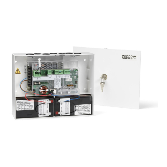
Structure of the smoke panel The WSC 104 contains a power supply unit (SMPS) type WCA 1P1, and a main card type WSA 1SS with input, output and auxiliary supply (AUX. The main card type WSA 1SS allows connections of 1 motor line and 1 keypad. ®... -
Page 5: Access Levels
2.1.1 Access levels Level Access to Who has access Public Everyone / General public You can see the smoke ventilation panel and break glass unit from the outside with the doors closed and locked Operation Chosen person e.g., building facility manger with You can open the break glass unit and reset the system a special key to break glass unit. -
Page 6: Accessories And Spare Parts
® ± 24V Actuator MotorLink Actuator WMX 803 / 804 / 813 / 814 / 823 / 826-1 WMX 803 / 804 / 813 / 814 / 823 / 826-2 WMX 803 / 804 / 813 / 814 / 823 / 826-3 WMX 803 / 804 / 813 / 814 / 823 / 826-4 WML 820/825 WML 860-1... -
Page 7: Technical Data
Technical data Technical data Output current (nominal) Secondary voltage Voltage 24V DC (±15%) Open circuit voltage (no load) 24V DC @ 20°C Ripple at max load 150mVp-p 24V DC, 500mA 1 motor line – the line can be either ±24V standard motor line or MotorLink ®... -
Page 8: Mounting
Break glass unit Up to 5 break glass units type WSK 50x can be connected to the panel, but only 1 WSK 501 / 502 per panel. Smoke detectors and ventilation keypads can only be connected to the break glass units type WSK 501 / 502. Smoke detectors and ventilation keypads cannot be connected to WSK 503 / 504. -
Page 9: Cables Into Housing
Cables into housing All connection terminals (except the mains terminals) are of the plug-in type. Connect the connection cables in accordance with the terminal plan. Ensure that the connections are made correctly. Incorrect cable clamping, mixing up numbers or colours could lead to malfunctions of the control panel or of the external components. -
Page 10: Formula For The Calculation Of The Maximum Actuator Cable Length
8.2.1 Formula for the calculation of the maximum actuator cable length Max. cable length = permissible voltage drop 2V (UL) x conductivity of copper (56) x cable cross section in mm actuator max. current total in amps (I) x 2 ®... - Page 11 ® When using actuators with MotorLink the max/total cable length is 50m regardless of the result of the above mentions formula. Actuators with MotorLink ® Do not use the PE wire / green/yellow wire! cable cross 3 wire 3 wire 5 wire 3 wire 5 wire...
-
Page 12: Cable Plan For Connection To Wsc 104
Cable plan for connection to WSC 104 The above plan shows the WSC 104 with ±24V standard actuators connected. Description of card and mains connection The panel includes a power supply unit (SMPS) and a main card. 10.1 Mains connection and power supply (WCA 1P1) WCA 1P1 - 100W SMPS unit The power supply is located under the main card. -
Page 13: Main Card Wsa 1Ss
10.2 Main card WSA 1SS The WSA 1SS contains the following: - 1 motor line for ±24V ® standard or MotorLink actuators - 1 input for keypads for comfort ventilation - 1 input for break glass units - 1 input for smoke detector - output for alarm signal - output for fault signal to Fire Alarm System... - Page 14 MotorLink ® actuators Examples with actuators per motor line Ex. 1: 4 pcs. WMX 823-1 Ex. 2: 2 pcs. WMU 882-2 Ex. 3: 3 pcs. WMU 826-3 ® Allowed actuator combinations on a MotorLink motor line The motor line can be connected to one of the below shown combinations. -1 (single): one window with one single window actuator.
- Page 15 For connection of break glass unit type WSK 50x. Data 5.1 24V 5.2 Communication 5.3 0V Up to 5 break glass units type WSK 503 or WSK 504 can be connected to the line. If keypad and smoke detector are to be connected to the break glass unit, WSK 501 or WSK 502 are to be used. Max one of these break glass unit on the panel, the remaining units (up to four) must be of type WSC 503 or WSC 504.
- Page 16 Connection of different types of smoke detectors to CompactSmoke™ Smoke detector type WSA 311 Hekatron Hekatron MSD 523 SSD 521/a (max 5 pcs) (WSA 200 6101) X6.1 In + Connect to WSA 1SS X6.2 Com - Com - Connect to WSK In + Com –...
- Page 17 For connection of rain sensor. Input circuit (simplified) Connection of wind / rain sensors type WLA 330 or rain sensor WLA 331. Data 9.1 24V 9.2 Rain (potential free / dry contact) (10kΩ resistor is to be moved to the Rain sensor) 9.3 GND / 0V With the default values are input:...
-
Page 18: Dip Switch Configuration
DIP switch configuration For easy configuration the smoke panel includes 8 DIP switches. The factory settings for all the DIP switches is OFF. Description on Description DIP switch position Possible switch the panel consequence No 230V No 230V window ON: No change in position in case of power This function window pos. -
Page 19: Configuration Of Panel
Configuration of panel The smoke panel is configured by pressing the two keys ”↑” and ”↓” on the main card, at the same time for 5-10 seconds. The smoke panel must be configured After re-installation, changes, or change of actuators ®... - Page 20 Example of an error message ”7 blinks – 1sec. pause – 2 blinks – 1 sec. pause – 1 blinks”. There is an error on a local input. The error is on input X9.1, to which a rain sensor might be connected. The error is due to no connection to the sensor.
-
Page 21: Fault Indication On Break Glass Unit
14.2 Fault indication on break glass unit If the smoke panel loses the mains connection (230V), the green LED on the break glass unit (WSK 501 / 502 / 503 / 504) will flash. The green LED will flash until the system goes into alarm (check power supply (error message 10.2)). With the standard settings it can take up to 10min before the loss of connection is registered. -
Page 22: Ventilation Keypad
16.4 Ventilation keypad Closely observe the actuators during opening and closing. They must not be impaired in any position by the building structure. Observe that the actuator cables are not being subject to pulling or pinching. Check each ventilation keypad individually. 16.5 Break glass unit WSK 50x a) Open the door and press the black Open button. -
Page 23: Maintenance Agreements
17.1 Maintenance agreements Be aware that regular inspection of smoke ventilation systems is a legal requirement. The legislation requires that the smoke ventilation system's owner inspects and tests the system once every year. WindowMaster offer maintenance agreements for the smoke ventilation system and every year we inspect the complete system to ensure it complies with the applicable legislation. -
Page 24: Appendix A - Wsc 104 S 0101 - Dip Switch Setting Log
Appendix A - WSC 104 S 0101 – DIP Switch setting log To keep the smoke panel in compliance with ISO 21927-9, changing the DIP switch setting must be logged. Below table can be used to log the changes. DIP switch DIP switch DIP switch DIP switch...
Need help?
Do you have a question about the CompactSmoke WSC 104 and is the answer not in the manual?
Questions and answers