
Related Manuals for PKP DP01


Summary of Contents for PKP DP01
- Page 1 Instruction Manual DP01 Paddle-Type Flow Switch PKP Prozessmesstechnik GmbH Borsigstraße 24 D-65205 Wiesbaden-Nordenstadt Tel.: ++49-(0)6122-7055-0 Fax: ++49-(0)6122-7055-50 Email: info@pkp.de...
-
Page 2: Table Of Contents
The series DP01 flow switch devices should not be deployed as the sole agents to prevent dangerous conditions occurring in plant or machinery. Machinery and plant need to be designed in such a manner that faulty conditions and malfunctions do not arise that could pose a safety risk for operators. -
Page 3: General Installation Instructions
Qualified Personnel The DP01 devices may only be installed by trained, qualified personnel who are able to mount the devices correctly. Qualified personnel are persons, who are familiar with assembling, installation, placing in service and operating these devices and who are suit- ably trained and qualified. -
Page 4: Flow Switch With Pipe Section (Types Dp01.1, Dp01.2 And Dp01.3)
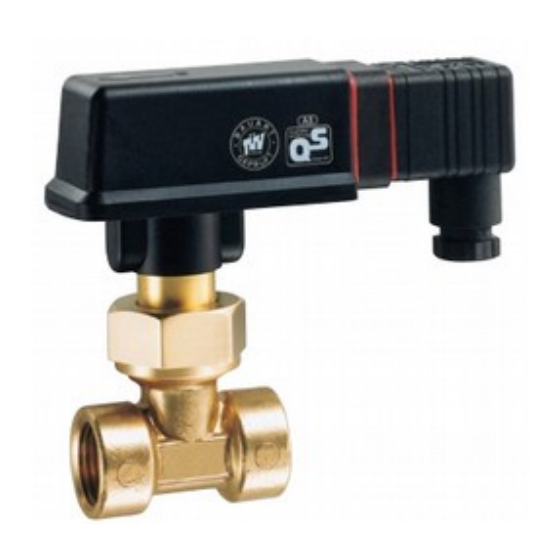
Flow Switch with Pipe Section (Types DP01.1, DP01.2 and DP01.3) 1. The pipe section of the flow switch is installed in existing pipes like a valve. 2. The switching point adjustment range ins indicated on the nameplate. 3. The sealing of the brass or stainless steel pipe sections should be achieved with threaded seals (Teflon tape, surface coating, etc.) or with suitable sealing rings... -
Page 5: Adjusting The Switching Unit (Figs. 14 To 16)
Now carefully tighten the locking screw • again. After setting the switching point, we • recommend securing the locking screw with lacquer or screw locking lacquer. Close the cover again until it clicks into • place. DP01 Instruction manual 07/2021 page 5... -
Page 6: Electrical Connection
4,5 to 10 mm. You must also ensure that all seals on the device plug (pos. 3, 4 and 9) are inser- • ted correctly. Reed contact Connected to PIN 1 und PIN 2 DP01 Instruction manual 07/2021 page 6... -
Page 7: Technical Data
O-Ring V-Seal -------------------------- ------------------------ EPDM All other relevant technical data (e.g. type designation, pressure rating, max. temperature, electrical connection values and switching point adjustment ranges) can be found in the technical appendix. DP01 Instruction manual 07/2021 page 7... -
Page 8: Installation Instructions For Paddle-Type Flow Switch Series Dp01.3
Before installation, check whether the material of the paddle flow switch is suitable for the medium to be measured! The paddle-type flow switch of the series DP01.3.. are special devices with integrated microswitch 250 V / 5 A, AC (mac.). - Page 9 Description: Typical application: The model DP01 flow switches operate according to the pad- The DP01 paddle flow switch is suitable for monitoring the dle principle. The flowing liquid pushes against the surface switching point of low-viscosity liquids.
- Page 10 +/- 15 %) Order number: DP01. 2. 25. 0. 0. Paddle type flow switch DP01.1.: with brass- or stainless steel T-fitting and reed contact Version: 1 = with T-fitting, brass or st. steel (reed contact) Nominal Connection...
- Page 11 Dimensions and Materials: DP01.1.: with brass- or stainless steel T-fitting and DP01.2.: with PVC- T-fitting and reed contact reed contact Nominal brass version st. steel version size Connection DN 15 G 1/4 DN 20 G 3/8 DN 25 G 1/2...
- Page 12 DP01.3.: with brass-T-fitting and microswitch DP01.4.: without T-fitting, screw-in thread 1/2“, installation length 51 mm, reed contact Material: Connection G 3/8 female DP01.4.1. DP01.4.2. G ½ female Body, paddle brass st. steel 1.4571 G ½ male Process brass st. steel1.4571 G ¾...
Need help?
Do you have a question about the DP01 and is the answer not in the manual?
Questions and answers