
Related Manuals for PKP DS52


Summary of Contents for PKP DS52
- Page 1 Instruction Manual DS52 Low Cost Variable Area Flow Switch PKP Prozessmesstechnik GmbH Borsigstraße 24 D-65205 Wiesbaden-Nordenstadt Tel.: ++49-(0)6122-7055-0 Fax: ++49-(0)6122-7055-50 Email: info@pkp.de...
-
Page 2: Table Of Contents
In particular, applications in which shock loads occur (e.g. clocked operation) should be discussed and checked beforehand with our technical personnel. The devices of the DS52 series must not be used as the sole means of preventing dan - gerous conditions on machines and systems. -
Page 3: Functional Description
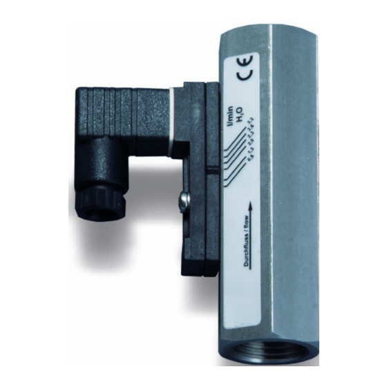
Functional Description The devices of the DS52 series operate according to the principle of the variable area flow meter. A float is moved by the flow of the medium and its integrated magnets generate a magnetic field. -
Page 4: Installation And Commissioning
10 x DN, 5 x DN behind the device. Never reduce the pipe diameter directly in front • of the unit! In the case of liquid media, take suitable measures to ensure that the device is • vented. DS52 Instruction manual 02/2019 page 4... -
Page 5: Electrical Connection
Protection class IP65 when using the DIN 43650 plug socket is only guaranteed in conjunction with cable diameters of 6 - 8 mm. Switch contact with cable The wires of the connection cable are numbered according to the above connection dia - gram. DS52 Instruction manual 02/2019 page 5... -
Page 6: Adjustment Of The Switching Point
The current state of the switching contact can be determined e.g. with a continuity • tester. The states of the switching contact refer to the normally open contact (N/O). • DS52 Instruction manual 02/2019 page 6... -
Page 7: Maintenance And Care
In most cases, rinsing with a clean medium is sufficient for cleaning. In stubborn • cases (e.g. limescale deposits), it can be cleaned with commercially available cleaners, provided these do not attack the materials of the device. Attention: Opening the device voids the warranty claim! DS52 Instruction manual 02/2019 page 7... -
Page 8: Troubleshooting
Request a conversion table or a media specific scale • 2. Incorrectly reduced Reduce according to "Installation and Commissioning” • 3. Device dirty Clean the unit • 4. Device defective Return the instrument for repair / calibration • DS52 Instruction manual 02/2019 page 8... - Page 9 Connecting devices equipped with Reed switches Reed switches are basically designed for small contact ratings. To connect a load with higher power consumption it is indispensable to use a contact protection relay (e.g. our series MSR01) If you connect directly a load to a Reed contact the following recommendations should be considered. None of the contact rating values printed on the switching unit must not to be exceeded, even momentarily.
- Page 10 Connecting to a PLC There is no need for protective measures by connecting the Reed switch to a PLC. The Reed contacts are plated by Tunsten, Gold, and Rhodium located in a protective atmosphere. They can be directly connected to the input terminals of a PLC without problems. RC-Circuits as protective measures (Boucherot cell, Snubber) In practice the following values of resistor/capacitor cells give good results.
- Page 11 100 °C Description: Applications: The flow switch model DS52 works according to a modified The variable area flow switch model DS52 is used for variable area principle. The float is guided in a cylindrical monitoring the flow of low viscosity liquids, e.g. in cooling measuring tube by means of a spring.
- Page 12 Variable Area Flow Switch Connection: 1 = G 1/4 female 2 = G 1/2 female Measuring range: DS52.1 only (G 1/4 connection N/O contact only): W101 = 5...60 ml/min W102A = 40...130 ml/min W106 = 0,1...0,6 l/min = 0,2...1,2 l/min = 0,4...2 l/min...
Need help?
Do you have a question about the DS52 and is the answer not in the manual?
Questions and answers