Table of Contents
Advertisement
Advertisement
Table of Contents
Troubleshooting

Related Manuals for Huayu HY-600-PRO


Summary of Contents for Huayu HY-600-PRO
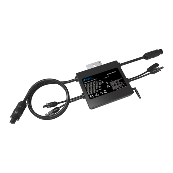
- Page 1 Photovoltaic Grid-connected Microinverter(Built-in WIFI) HY-500-PRO HY-600-PRO HY-600-PRO-127V Installation/User Manual Add:No.456, Xingning Road, Ningbo315100, P.R,China Tel : +86-574-8925 8801 E-mail: sales@huayu-energy.com P.C : 315100 Web : www.huayu-energy.com Ver: 1.4, 2020-02...
-
Page 2: Table Of Contents
Table of Contents Important Safety Instructions 01-03 Safety Instructions Radio Interference Statement The Meaning of Symbols Microinverter System Introduction 03-05 Microinverters Maximize PV Energy Production More Reliable than Centralized or String Inverters Simple to Install Microinverter Introduction Microinverter System Installation 06-09 Additional Installation Components Required Parts and Tools from You... -
Page 3: Important Safety Instructions
Important Safety Instructions This manual contains important instructions to follow during installation and maintenance of the Photovoltaic Grid-connected Inverter(Microinverter).To reduce the risk of electrical shock and ensure the safe installation and operation of the Microinverter, the following symbols appear throughout this document to indicate dangerous conditions and important safety instructions. -
Page 4: Radio Interference Statement
but maintain the protective earthing conductor in the branch circuit breaker connect to the inverter ,then disconnect the DC inputs. In any circumstance, do not connect DC input when AC connector is unplugged. Please install isolation switching devices on the AC side of the inverter. Radio Interference Statement CE EMC Compliance:The equipment can comply with CE EMC, which are designed to protect against harmful interference in a residential installation. -
Page 5: Microinverter System Introduction
CE mark is attached to the solar inverter to verify that the unit follows the provisions of the European Low Voltage and EMC Directives. Refer to the operating instructions. Person adequately advised or supervised by an electrically skilled person to enable him or her to perceive risks and to avoid hazards which electricity can create. -
Page 6: Microinverters Maximize Pv Energy Production
1200G / 1300G Module Meter Microinverter Distribution WIFI Boost Neutral Ground Router Monitoring system NOTE: If the wireless signal in the area where the microinverter is weak is weak, it is necessary to add a wifi signal booster at a suitable place between the router and the microinverter. -
Page 7: Simple To Install
HY-500-Pro 50/60Hz,230V 60,72 Cell 8 for 25A breaker MC-4 Type or Customize 50/60Hz,208/240V 60,72 Cell 8 for 25A breaker MC-4 Type or Customize HY-600-Pro 50/60Hz,127V 60,72 Cell 8 for 25A breaker MC-4 Type or Customize HY-600-Pro-127V HY-1000-Pro 50/60Hz,230V 60,72 Cell... -
Page 8: Microinverter System Installation
Microinverter System Installation A PV system using Microinverters is simple to install. Each Microinverter easily mounts on the PV racking, directly beneath the PV module(s). Low voltage DC wires connect from the PV module directly to the Microinverter, eliminating the risk of high DC voltage.Installation MUST comply with local regulations and technical rules. -
Page 9: Installation Procedures
Installation Procedures a. Install an appropriate junction box at a suitable location on the PV racking system (typically at the end of a branch of modules). b. Connect the open wire end of the AC cable into the junction box using an appropriate gland or strain relief fitting. - Page 10 WARNING: Prior to installing any of the microinverters, verify that the utility voltage at the point of common connection matches the voltage rating on microinverter label. WARNING: Do not place the inverters (including DC and AC connectors) where exposed to the sun, rain or snow, even gap between modules.Allow a minimum of 3/4 (1.5cm.) between the roof and the bottom of the Microinverter to allow proper air flow.
-
Page 11: Microinverter System Operating Instructions
NOTE:When plugging in the DC cables, if AC already available,the Microinverter should immediately blink red light and will start work within the setting time (default 60 seconds). If AC is not available,the red light will blink 3 times quickly and repeat after one second until AC is connected. -
Page 12: Troubleshooting
3. The units should start blinking red one minutes after turning on the AC circuit breaker. Then blue led blinking. This means they are producing power normally, the faster blinking of the blue led means more power generated. 4. Configure the internal wifi module according to its user manual. 5. -
Page 13: Troubleshooting A Non-Operating Microinverter
GFDI Error A four time red LED indicates the Microinverter has detected a Ground Fault Detector Interrupter (GFDI) error in the PV system. Unless the GFDI error has been cleared, the LED will remain four times blinking. Other Faults All other faults can be reported to the website and APP. WARNING: Never disconnect the DC wire connectors under load. - Page 14 2. Diagnosing from the network: a. No-Data-Display: The website and APP don't display any data.Check the network configuration. b. Only display microinverter is online but no data.This maybe because server is updating. To troubleshoot a non-operating Microinverter, Follow the steps below in order: 1.
-
Page 15: Replacement
Replacement Follow the procedure to replace a failed Microinverter A. Disconnect the Microinverter from the PV Module, in the order shown below: 1. Disconnect the AC by turning off the branch circuit breaker. 2. Disconnect the AC connector of the microinverter. 3. -
Page 16: 500G/600G Microinverter Datasheet
500G/600G Microinverter Datasheet Model HY-500-Pro HY-600-Pro HY-600-Pro-127V Input Data (DC) Recommended input power(STC) 210~400W(2 Pieces) 210~350W Maximum input DC voltage 25~55V 25~55V MPPT Voltage Range Operating DC Voltage Range 20~60V 20~60V Max DC short circuit current Max input current 10.4×2 10.4×2... -
Page 17: 1200G/1300G Microinverter Datasheet
1200G/1300G Microinverter Datasheet Model HY-500-Pro HY-600-Pro HY-600-Pro-127V Input Data (DC) Recommended input power(STC) 210~400W(4 Pieces) Maximum input DC voltage MPPT Voltage Range 25~55V Operating DC Voltage Range 20~60V Max DC short circuit current Max input current 10.4×4 Output Data (AC) -
Page 18: Wiring Diagram
Wiring Diagram - 16 -... - Page 19 - 17 -...
- Page 20 - 18 -...
- Page 21 - 19 -...
- Page 22 - 20 -...
- Page 23 - 21 -...
Need help?
Do you have a question about the HY-600-PRO and is the answer not in the manual?
Questions and answers