
Related Manuals for SANKI S-CON FRAT BF


Summary of Contents for SANKI S-CON FRAT BF
- Page 1 S-CON FRAT (BF,BFG and BFGS Models) ® S-CON (BT and BTG Models) ® OPERATING AND SERVICE MANUAL...
-
Page 2: Table Of Contents
Thank you very much for purchasing our S-CON FLAT/BT. To use the machine ® properly, please read this operating and service manual carefully before use. Keep the manual where the machine is installed, so that it may be referred to when needed. TABLE OF CONTENTS 1.Caution When Handling …………………………………... - Page 3 Upon delivery of this product, check the package contents to ensure the product matches your order. If the delivered items do not match your order, please contact our local agent directly before use. NOTE: When referring to this manual, confirm the conveyor model code and read the appropriate pages.
-
Page 4: 1.Caution When Handling
CAUTION WHEN HANDLING FOR YOUR SAFE USAGE A. Prior To Use CAUTION : Improper handling of the conveyor may result in physical injury or damage! ■Transport and assembly When transporting and assembling the conveyor, pay special attention not to drop it in order to avoid physical injury or damage. - Page 5 B. During Operation WARNING: Improper handling of the conveyor could result in serious physical injury or damage! ■Do NOT touch the conveyor when it is running There is considerable risk of being caught and injured by the conveyor. ■Do NOT ride on or climb on the conveyor/Do NOT go under the conveyor There is considerable risk of falling or being caught and injured by the conveyor.
- Page 6 ■WARNING LABELS etc. AND ATTACHMENT POSITIONS For standard machines, warning labels etc. and their attachment positions are as follows: 1. WARNING LABELS Label Instruction Label classification DANGER ■KEEP HANDS OUT WHILE MACHINE IS RUNNING There is considerable risk of being caught and injured by the conveyor.
- Page 7 2. ATTACHMENT POSITIONS OF WARNING LABELS etc. (eg S-CON FLAT BF model) ® WARNING label B-1 DANGER label A-1 (attached on frame top at intervals of 3 to 6m) (attached on opposite side of frame) WARNING label B-1 WARNING label B-1 DANGER label A-1 Connector (attached on frame top at intervals of 3 to 6m)
-
Page 8: 2.Component Names
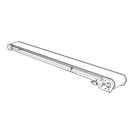
COMPONENT NAMES 2-1. S-CON FLAT (BF, BFG and BFGS models) ® 1. Portable Type S-CON FLAT ® Applied models:BF model (Motor pulley driving type), BFG model (Geared motor driving type) Unit: mm Carrying roller pitch Take-up stroke:300 Machine length:L Tail pulley Connector Motor pulley 2. - Page 9 (2)Fixed Inclined Type Applied models:BFGS model (Geared motor driving type) NOTE: These are diagrams of head drive type BFGS model with center take-up unit of 500mm-stroke and belt feeder. Top view Length of horizontal area:L2 Drive pulley Bent unit (Head pulley) Head drive unit Belt feeder length Side view...
- Page 10 TAKE-UP TYPE OF S-CON FLAT (BF, BFG and BFGS models) ® :Motor pulley/Geared motor ● Tail take-up unit HEAD DRIVE TYPE CENTER DRIVE TYPE NOTE: Snub pulleys of head and tail units are attached for reversible operation only. ● Vertical center take-up unit HEAD DRIVE TYPE <Take-up stroke: 100mm>...
- Page 11 2-2. S-CON BT(BT and BTG models) ® Applied models: BT model (Motor pulley driving type), BTG model (Geared motor driving type) NOTE: These are diagrams of BT model. ● Geared motor driving type S-CON BT (BTG model) ®...
- Page 12 ● Hopper unit of S-CON BT (BT and BTG models) ® (eg 2-roller-trough type of 350 to 450mm in belt width) NOTE : Assembly and installation of S-CON BT hopper unit: ® If it is necessary to assemble and install hopper unit, perform as follows: 1.On right and left sides of hopper unit, remove hopper side covers(*1) by loosening attachment bolts(*2)(2 bolts on each side).
-
Page 13: 3.Assembly
ASSEMBLY 3-1. FRAME ASSEMBLY For machine length exceeding 4.7m, frame is delivered divided. In this case assemble frame as follows: 1.Move tail pulley(*4) toward head unit by turning take-up screws(*3)of tail frame(*2). (For center take-up type, to loosen belt, move take-up pulley by turning take-up screws.) 2.Remove return roller(*5) of tail frame(*2) together with brackets by loosening attachment bolts and nuts on frame undersurfaces. - Page 14 NOTE: 1. Installation of endless belt delivered in separate packaging For machine length of 15.01m or more, endless belt (loop-form belt) is delivered in separate packaging. When installing this type belt to frame, in step 2 on previous page, additionally remove return roller, brace and snub pulley(*8) of head frame.
- Page 15 NOTE: 3. Bent unit assembly of fixed inclined type S-CON FLAT(BFGS model) ® When bent unit of BFGS model is delivered divided, assemble it as follows: (1) On both sides of bent unit, loosen right and left angle adjustment fixing bolts(*2)(2 bolts on each side) of bent frames(*1).
- Page 16 3-2. ELECTRICAL WIRING For standard machines, electrical wiring is provided as follows: -Motor pulley driving type: from motor pulley to connector only -Geared motor driving type: to geared motor lead wire only (Further electrical wiring, electrical equipments, etc. are optional.) Further electrical wiring should be carried out by appropriately qualified specialists.
- Page 17 3-3. INSTALLING STANDS(OPTIONAL) 1. Installation of horizontal fixed stand (EF model) and horizontal portable stand (EC model) Install horizontal fixed stand (EF model) or horizontal portable stand (EC model) to frame by fixing stand brackets to frame undersides with attachment bolts and nuts(2 sets on each side), as shown in figure right.
- Page 18 2. When installing portable inclining tail stand or relocating conveyor with portable inclining tail stand installed, set inclined-angle at minimum, i.e. set machine height at minimum. 3. When changing inclined-angle, loosen fixing wing bolt(*1)(one bolt on one side)and turn handle(*2). After adjustment, be sure to retighten fixing wing bolt(*1).
- Page 19 3-4. INSTALLING BELT FEEDER (OPTIONAL) For S-CON FLAT BFGS model (Fixed inclined type) ® Belt feeder unit is delivered in separate packaging. Install it to conveyor main body following procedure below: 1. Changing installation angles of interlocking plates or interlocking pulley plates For smooth material transfer between inclined conveyor main body and belt feeder, change installation angles of interlocking plates or interlocking pulley plates depending on direction of belt travel, as follows.
- Page 20 2. Installing belt feeder unit to conveyor main body Insert both interlocking pulley plates(*7) into tail frame end of conveyor main body, and fix them with attachment bolts and nuts(*9)(2 sets on each side). NOTE: 1. If interlocking drive chain is not installed, install it to interlocking sprockets of conveyor main body and belt feeder unit.
-
Page 21: 4.Running The Conveyor
RUNNING THE CONVEYOR 4-1. BEFORE TURNING ON START SWITCH Before turning on start switch, be sure to check items below: 1. Loose/missing bolts or nuts: may cause parts to come off conveyor or frame to be bent. Before operation, retighten bolts and nuts. - Page 22 4-2. AFTER TURNING ON START SWITCH When the following problems occur after turning on start switch, perform as follows: 1. Belt does not run (Motor pulley does not rotate): Turn off start switch and power supply immediately, or motor pulley may burn out. Check electrical wiring and motor pulley.
-
Page 23: 5.Taking Up The Belt
TAKING UP THE BELT When belt is slackened off, take up the belt following procedure below: 5-1. TAKING UP BELT USING TAIL TAKE-UP UNIT For S-CON FLAT (BF, BFG and BFGS models), S-CON BT (BT and BTG models) Ⓡ Ⓡ S-CONⓇBT (BT and BTG models) For machines with tail take-up unit, move tail pulley(*2) together with take-up brackets(*3) outward by turning right and left take-up screws(*1) clockwise with a spanner. - Page 24 3. Machine with double horizontal center take-up unit First move either of take-up pulleys(*9 or *11) by turning right and left take-up screws(*8 or *10) counterclockwise with a spanner. Next similarly move the other take-up pulley(*9 or *11) by turning right and left take-up screws(*8 or *10) counterclockwise.
-
Page 25: 6.Belt Alignment Adjustment
BELT ALIGNMENT ADJUSTMENT When belt is not properly aligned, check machine condition and adjust belt alignment as follows: 6-1. PRIOR CHECKING 1. Frame: Confirm full length of frame is level on top, straight and not bent in any place. Particularly, carefully check frame joints. - Page 26 2. Belt alignment adjustment of conveyor for normal directional use Depending on machine type, adjust belt alignment following steps A to L below. Finish adjustment when belt is properly aligned. It may not be necessary to proceed to further steps. - Head drive type machine with tail take-up unit: Perform steps A to E .
- Page 27 B Adjustment using tail pulley (→See fig. 6, and fig. 1 and fig. 2 on p.26.) On side to which belt is deviating, move tail pulley(*9) shaft end slightly outward by turning take-up screw(*8) clockwise with a spanner. Tail pulley(*9) will then be set diagonally and belt will center itself. Alternatively adjust on opposite side.
- Page 28 ● For S-CON BT (BT and BTG models) Ⓡ For standard machines, it is impossible to adjust carrying rollers. NOTE: When adjustable bracket(*1)(optional) of carrying roller(*3) is attached, loosen attachment bolts(*2) and move carrying roller(*3) together with bracket(*1) slightly diagonally. Belt will then center itself.
- Page 29 G Adjustment using take-up pulley of center take-up unit ● For vertical center take-up unit (→See fig. 11, fig. 9 and fig. 10 on p.28.) On side to which belt is deviating, move take-up pulley(*13) shaft end slightly downward by turning take- up screw(*12).
- Page 30 When belt is deviating to opposite side of cabtire cable connector, loosen lock nut(*3) of adjustment bolt(*2). Then slightly move motor pulley(*1) shaft end towards tail unit by turning adjustment bolt(*2). Motor pulley(*1) will then be set diagonally and belt will center itself. When belt is deviating to cabtire cable connector side, similarly move motor pulley(*1) shaft end towards head unit by turning adjustment bolt(*2) in reverse direction.
- Page 31 3. Belt alignment adjustment of reversible conveyor For S-CON FLAT (BF, BFG and BFGS models) Ⓡ First check belt deviation referring to “1. Checking belt deviation”, p. 25. Then adjust belt alignment depending on direction of belt travel as follows, and finish adjustment when belt is properly aligned. It may not be necessary to proceed to further steps.
- Page 32 (2) When traveling in reverse direction (→See fig. 21 and fig. 22.) Perform steps N , D , F and E in this order. M Adjustment using snub pulley of head unit (→See fig. 23, fig. 21 and fig. 22.) Reversible conveyor is usually provided with snub pulley in head unit (tail unit in reverse operation).
-
Page 33: 7.Belt Replacement
BELT REPLACEMENT Depending on replacement belt condition, there are two kinds of procedures as follows: ・Replacing with endless belt (preprocessed loop-form belt) ・Carrying out belt endless processing at site where conveyor is used Replace belt as follows depending on replacement belt condition, drive type and take-up type. 7-1. - Page 34 NOTE: 1. Inserting belt into head drive type geared motor driving type machine: Remove chain cover. Next remove lower cover, brace and snub pulley(*6) of head unit, and then remove drive unit side plate(*7 or *13) following procedures below. After inserting belt into machine, reinstall removed parts in reverse order.
- Page 35 2. Center drive type S-CON FLAT with center take-up unit Ⓡ (1)To slacken belt fully, move take-up pulley(*2) by turning right and left take-up screws(*1). (2)If covers (lower & side cover etc.) are attached, remove them all. (3)Remove all the braces(*3) and two snub pulleys(*4). (If it is difficult to insert belt into machine, also remove take-up pulley(*2) by pulling out split pins.) (4)Remove all the return rollers.
-
Page 36: 8.Motor-Pulley/Geared-Motor Replacement
MOTOR-PULLEY/GEARED-MOTOR REPLACEMENT 8-1. MOTOR PULLEY REPLACEMENT NOTE: Before starting procedures below, be sure to stop conveyor and switch off power supply. Pay special attention not to drop motor-pulley/geared-motor in order to avoid injury. 1. To slacken belt fully, move take-up pulley by turning right and left take-up screws. 2. - Page 37 8-2. GEARED MOTOR REPLACEMENT NOTE: Before starting procedures below, be sure to stop conveyor and switch off power supply. Pay special attention not to drop motor-pulley/geared-motor in order to avoid injury. 1. Remove chain cover(*1) by loosening attachment bolts. (If lower/top cover(*2) is attached to drive unit, remove it.) 2.
- Page 38 ● Center drive type geared motor driving type S-CON FLAT (BFG and BFGS models) ® (eg Take-up stroke of 500mm)
-
Page 39: 9.Removal Of Pulleys And Rollers
REMOVAL OF PULLEYS AND ROLLERS 9-1. REMOVAL OF PULLEYS Slacken belt by turning take-up screws, and remove each pulley as follows: 1. Snub pulley removal fig.1: Snub pulley of head unit ● Snub pulley in head unit of head drive type machine (eg Motor pulley driving type machine) (See fig. - Page 40 fig.5: S-CON FLAT (BF, BFG and BFGS models) 9-2. REMOVAL OF ROLLERS ® (For flat rollers) 1. Carrying roller removal ● S-CON FLAT (BF, BFG and BFGS ® models) (See fig. 5.) Remove snap pin(*2) from one end of carrying roller(*1) shaft with a tool such as a pair of pliers.
-
Page 41: 10.Inspection And Maintenance
INSPECTION AND MAINTENANCE To use conveyor performance fully and make its service life longer, it is necessary to carry out inspection and maintenance properly. For electrical matter, inspection and maintenance should be carried out by appropriate qualified specialists. 10-1. PROBLEMS AND REMEDIES PROBLEM CAUSE REMEDY... - Page 42 PROBLEM CAUSE REMEDY (2) Connector Breakage Replace connector. (Be sure to start and stop conveyor with switch, not with connector.) (3) Scraper Abrasion, Materials or foreign substances have stuck to a. Remove any foreign matter so that scraper breakage scraper. rubber plate will touch belt correctly.
- Page 43 PROBLEM CAUSE REMEDY (6) …cont. from “Motor pulley (or Geared motor)” When motor pulley (or geared motor) runs unloaded 1. Motor pulley (or Wiring failure a. Switch positions of any two of three power geared motor) supply leads. rotates in wrong b.
- Page 44 10-2. ITEMS FOR REGULAR INSPECTION CHECKING CHECKING PART TO CHECK THINGS TO CHECK FOR REMEDY PERIOD METHOD Daily Belt Foreign substances on surface Visual inspection Remove any foreign matter. and undersurface Cleaning Getting jammed Visual inspection Check and correct belt condition. Damage on surface Visual inspection Investigate cause and repair.
- Page 45 Taking Up Drive Chain When drive chain is slackened off, take up drive chain as follows: NOTE: Before starting procedures below, be sure to stop conveyor and switch off power supply. Remove chain cover. Loosen attachment bolts and nuts(*2)(4 sets) of motor base(*1). Slightly move motor base(*1) together with geared motor inward by turning adjustment bolt(*3) as shown in figure right.
- Page 46 MEMO...
- Page 47 MEMO...
- Page 48 Contact us ● Particular attention is given to the manufacture and transportation of SANKI conveyors. However, if you need any information about the use or failure of the machine or any other matters, please contact our customer service. Also do not hesitate to ask us for information about conveyors in general.
Need help?
Do you have a question about the S-CON FRAT BF and is the answer not in the manual?
Questions and answers