
Related Manuals for SANKI S-CON BABY SBF


Summary of Contents for SANKI S-CON BABY SBF
- Page 1 S-CON BABY ® (SBF and SBT models) (BFS and BTS models) OPERATING AND SERVICE MANUAL...
-
Page 2: Table Of Contents
Thank you very much for purchasing our S-CON BABY. To use the machine ® properly, please read this operating and service manual carefully before use. Keep the manual where the machine is installed, so that it may be referred to when needed. - Page 3 Upon delivery of this product, check the package contents to ensure the product matches your order. If the delivered items do not match your order, please contact our local agent directly before use. NOTE: When referring to this manual, confirm the conveyor model code and read the appropriate pages.
-
Page 4: 1.Caution When Handling
CAUTION WHEN HANDLING FOR YOUR SAFE USAGE A. Prior To Use CAUTION : Improper handling of the conveyor may result in physical injury or damage! ■Transport and assembly When transporting and assembling the conveyor, pay special attention not to drop it in order to avoid physical injury or damage. - Page 5 B. During Operation WARNING: Improper handling of the conveyor could result in serious physical injury or damage! ■Do NOT touch the conveyor when it is running There is considerable risk of being caught and injured by the conveyor. ■Do NOT ride on or climb on the conveyor/Do NOT go under the conveyor There is considerable risk of falling or being caught and injured by the conveyor.
- Page 6 ■WARNING LABELS etc. AND ATTACHMENT POSITIONS For standard machines, warning labels etc. and their attachment positions are as follows: 1. WARNING LABELS Label Instruction Label classification DANGER ■KEEP HANDS OUT WHILE MACHINE IS RUNNING There is considerable risk of being caught and injured by the conveyor.
- Page 7 2. ATTACHMENT POSITIONS OF WARNING LABELS etc. (eg S-CON BABY SBF model) ® WARNING label B-1 WARNING label C-1 Serial number and model label ob. NO : CAUTIONS FOR OPERATION TYPE 1. BEFORE OPERATION, TAKE MEASURE SPECIFIC ATIONS OF INSULATION RESISTANCE, FIRST. CAPACITY KG/M BE SU R E TO GR OU N D FR OM TH E...
-
Page 8: 2.Component Names
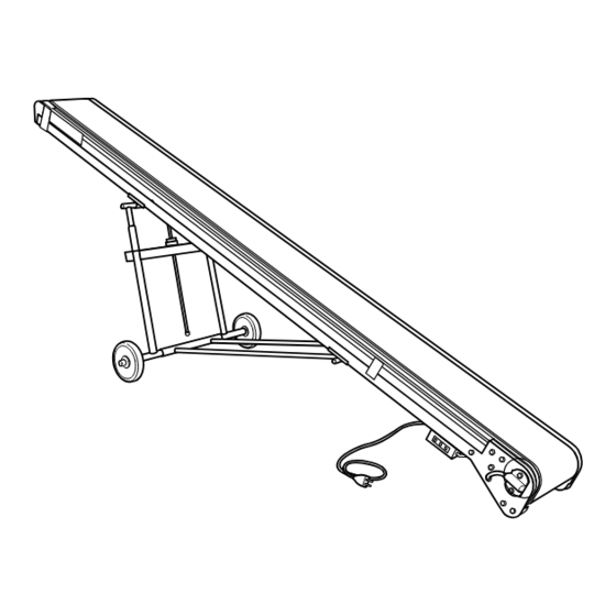
COMPONENT NAMES 2-1. FLAT TYPE S-CON BABY (SBF and BFS models) ® NOTE: These are diagrams of flat type S-CON BABY SBF model ® with portable inclining stand BH30 (optional). NOTE: 1. When installing portable inclining stand (BH30 or BW30 model) (optional) to flat type S-CON BABY (SBF model), ®... - Page 9 2-2. TROUGH TYPE S-CON BABY (SBT and BTS models) ® NOTE: These are diagrams of trough type S-CON BABY SBT model ® with portable inclining stand BH30 (optional). NOTE: 1. When installing portable inclining stand (BH30 or BW30 model) (optional) to trough type S-CON BABY (SBT model), ®...
-
Page 10: 3.Assembly
ASSEMBLY 3-1. FRAME ASSEMBLY For machine length of 4.5m or less, machine is delivered assembled. (Support stand for transportation is attached under conveyor middle part. Remove or leave it attached for use.) For machine length exceeding 4.5m, machine is usually delivered divided into 2 sections. In this case, assemble machine as follows: 1. - Page 11 NOTE : Assembly and installation of hopper If hopper of trough type S-CON BABY (SBT and BTS models) is delivered in separate packaging, ® assemble and install it as follows: 1. On right and left sides of hopper, remove hopper side covers(*1) by loosening attachment bolts(*2)(2 bolts on each side).
- Page 12 3-2. ELECTRICAL WIRING Electrical wiring of standard S-CON BABY is provided with START/STOP push button switch and cabtire ® cable of 1m (with waterproof connector attached to the end) ● Flat type connector coming from motor pulley. (→ See figure below.) NOTE: For 200V three-phase source, machine is occasionally not provided with START/STOP push button switch, provided with flat type connector only.
- Page 13 3-3. INSTALLING STANDS (OPTIONAL) 1. Installation of horizontal fixed stand (EG30 model) and horizontal portable stand (EC30 model) Install horizontal fixed stand (EG30 model) or horizontal portable stand (EC30 model) to frame by fixing stand brackets to frame undersides with attachment bolts and nuts (2 sets on each side), as shown in figure right.
- Page 14 NOTE: 1. When installing portable inclining stand, be sure to place motor pulley on lower side (tail unit side) in order to prevent machine from toppling. 2. When installing portable inclining stand or relocating conveyor with portable inclining stand installed, set machine height at minimum. 3.
- Page 15 3. Installation of portable inclining stand (Wire winch type WH30 model) (1) Preparation for assembly and installation 1) When installing portable inclining stand, be sure to place motor pulley on lower side (tail unit side) in order to prevent machine from toppling. 2) In advance be sure to install EF30-25 type stand in head unit.
- Page 16 (3) Use range of wire winch type WH30 model ● Without portable inclining tail stand Machine At minimum At maximum Installation dimension Tipping load Type length Tipping Tipping Height Angle Height Angle at 20° (mm) load load 2,900 1,200 19.5° 96kg 1,550 28.5°...
-
Page 17: 4.Running The Conveyor
RUNNING THE CONVEYOR 4-1. BEFORE TURNING ON START SWITCH Before turning on start switch, be sure to check items below: 1. Loose/missing bolts or nuts: may cause parts to come off conveyor or frame to be bent. Before operation, retighten bolts and nuts. - Page 18 4-2. AFTER TURNING ON START SWITCH When the following problems occur after turning on start switch, perform as follows: 1. Belt does not run (Motor pulley does not rotate): Turn off start switch immediately, or motor pulley may burn out. Check electrical wiring and motor pulley.
-
Page 19: 5.Taking Up The Belt
TAKING UP THE BELT When belt is slackened off, take up the belt following procedure below: Move tail pulley(*2) together with take-up brackets(*3) outward by turning right and left take-up screws(*1) clockwise with a spanner. Belt will then be taken up. When turning take-up screws(*1), adjust them alternately, little by little, to keep their movement lengths the same. -
Page 20: 6.Belt Alignment Adjustment
BELT ALIGNMENT ADJUSTMENT When belt is not properly aligned, check machine condition and adjust belt alignment as follows: 6-1. PRIOR CHECKING 1. Frame: Confirm full length of frame is level on top, straight and not bent in any place. Particularly, carefully check frame joints. - Page 21 2. Belt alignment adjustment of conveyor for normal directional use Adjust belt alignment following procedure below. Start from step A , and finish adjustment when belt is properly aligned. It may not be necessary to proceed to further steps. A Adjustment using motor pulley (→ See fig. 3, fig. 1 and fig. 2.) On opposite side of cabtire cable, make adjustment depending on direction of belt deviation, as follows.
- Page 22 D Adjustment using return roller (→ See fig. 5, and fig. 1 and fig. 2 on p.21.) On side to which belt is deviating, find the closest return roller(*7) to tail unit. Loosen attachment bolts and nuts(*9, 2 sets on each side) of brackets(*8) of this return roller(*7). Then move return roller(*7) together with brackets(*8) slightly diagonally.
-
Page 23: 7.Belt Replacement
BELT REPLACEMENT Replace endless belt (loop-form belt) following procedure below: 1. To loosen belt, fully move tail pulley(*2) inward by turning take-up screws(*1). Remove entanglement prevention cover(*3), and remove tail pulley(*2) by loosening fixing bolts(*4). (→ See“9. REMOVAL OF PULLEYS AND ROLLERS”, p. 25.) 2. -
Page 24: 8.Motor-Pulley Replacement
MOTOR PULLEY REPLACEMENT NOTE: Before starting procedures below, be sure to stop conveyor and switch off power supply. Pay special attention not to drop motor-pulley/geared-motor in order to avoid injury. 1.To loosen belt, fully move tail pulley of tail unit inward by turning take-up screws. 2.Open lid of push-button switch(*1). -
Page 25: 9.Removal Of Pulleys And Rollers
REMOVAL OF PULLEYS AND ROLLERS 9-1. REMOVAL OF PULLEYS 1. Removal of tail pulley (take-up pulley) Fully loosen belt by turning right and left take-up screws(*2). Remove fixing bolts(*3) of right and left tail pulley(*1) shaft ends. Tail pulley may then be removed outward. 2. -
Page 26: 10.Inspection And Maintenance
INSPECTION AND MAINTENANCE 10-1. PROBLEMS AND REMEDIES To use conveyor performance fully and make its service life longer, it is necessary to carry out inspection and maintenance properly. For electrical matter, inspection and maintenance should be carried out by appropriate qualified specialists. PROBLEM CAUSE REMEDY... - Page 27 PROBLEM CAUSE REMEDY (2) Connector Breakage Replace connector. (Be sure to start and stop conveyor with switch, not with connector.) (3) Scraper Abrasion, breakage Materials or foreign substances have stuck a. Remove any foreign matter so that scraper to scraper. rubber plate will touch belt correctly.
- Page 28 PROBLEM CAUSE REMEDY (6) …cont. from “Motor pulley (or Geared motor)” When motor pulley (or geared motor) runs unloaded 1. Motor pulley (or Wiring failure a. Switch positions of any two of power supply geared motor) wires. rotates in wrong b.
- Page 29 10-2. ITEMS FOR REGULAR INSPECTION CHECKING CHECKING PART TO CHECK THINGS TO CHECK FOR REMEDY PERIOD METHOD Daily Belt Foreign substances on surface Visual inspection Remove any foreign matter. and undersurface Cleaning Getting jammed Visual inspection Check and correct belt condition. (→See NOTE 1.) Damage on surface Visual inspection...
- Page 30 MEMO...
- Page 31 MEMO...
- Page 32 Contact us ● Particular attention is given to the manufacture and transportation of SANKI conveyors. However, if you need any information about the use or failure of the machine or any other matters, please contact our customer service. Also do not hesitate to ask us for information about conveyors in general.
Need help?
Do you have a question about the S-CON BABY SBF and is the answer not in the manual?
Questions and answers