Texas Instruments TI-RSLK MAX User Manual
Dsp adapter board
Hide thumbs
Also See for TI-RSLK MAX:
- Construction manual (25 pages) ,
- Manual (10 pages) ,
- Construction manual (32 pages)
Advertisement
Table of Contents
Advertisement
Table of Contents

Related Manuals for Texas Instruments TI-RSLK MAX


Summary of Contents for Texas Instruments TI-RSLK MAX
- Page 1 DSP Adapter Board User Guide...
- Page 2 Contents Introduction ........................................... 2 Assembly ............................................1 Pin Map ............................................0 Out of the Box Experience ......................................1...
- Page 3 IoT and connectivity, and machine learning. The newest addition to the TI-RSLK MAX is a DSP Adapter Board that expands the learning kit's capabilities to include labs related to Digital Signal Processing (DSP).
- Page 4 TI-RSLK chassis board assembly c. 8-Channel QTRX Sensor aeeat for ROMI/TI RSLK d. Left Bumper Switch assembly for TI-RSLK MAX e. Right Bumper Switch assembly for TI-RSLK MAX Gearmotor and encoder assembly (2) g. 400-point breadboard with special mounting holes and four 1”- long #2-56 M-F aluminium standoffs (...
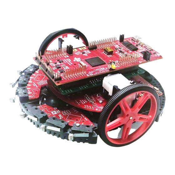
- Page 5 Assembly Launchpad Connectors J1, J2, J3, J4 Chassis Connections Launchpad Connectors J5, J6, J7, J8 Plug in the adapter board on top of the TI-RSLK Chassis. After, place the DSP Launchpad on top of the Adapter Board with the USB connector facing the back of the robot.
- Page 6 Pin Map...
- Page 7 Out of the Box Experience The program that is included in the DSP Adapter kit will utilize the motors and tachometers in the robot chassis to go straight until it hits an obstacle. The obstacle will be detected using the front bumpers. Once it hits an obstacle, it will turn left or right depending on the bumpers that are hit.
Need help?
Do you have a question about the TI-RSLK MAX and is the answer not in the manual?
Questions and answers