Advertisement
Quick Links
Advertisement

Related Manuals for Fnirsi DSO-TC3


Summary of Contents for Fnirsi DSO-TC3
- Page 1 DSO-TC3 三合一示波器 使用说明书 Digital Multimeter Instruction Manual...
- Page 3 目 录...
- Page 4 CATALOG...
- Page 5 用户须知 ●本说明书详细介绍了产品的使用方法以及注意事项和相关事宜, 在使 用本产品时请详细阅读手册, 以便发挥产品的最佳性能。 ●不要在易燃易爆的环境中使用仪器。 ●仪器更换的废旧电池和报废的仪器不可与生活垃圾一同处理, 请按照 国家或者当地的相关法律法规处理。 ●当仪器出现任何质量问题或者对使用仪器有疑问时, 可联系 “菲尼瑞斯 -FNIRSI” 在线客服或者厂家, 我们将在第一时间为你解决。 一、 产品简介 本产品将数字示波器、 电子元器件测试仪、 信号发生器、 通断测试、 电压测 量、 温湿度测量、 红外解码等功能巧妙地集成为一体, 配用大尺寸的彩色 点阵TFT显示屏, 内置可充电锂电池, 以小巧的体积带给用户更多、 更强 的实用功能, 同时具有很好的便携性。 二、 技术规格 2.1 整机主要规格与参数 显 示 屏 2.4英寸TFT彩屏, LED背光...
- Page 6 2.2 DSO数字示波器模式规格与参数 ●该示波器具有10M的实时采样率, 500K带宽 ●具有完整的触发功能 (单次、 正常、 自动) , 无论是对于周期模拟信号还 是非周期的数字信号都能运用自如。 ●最高可测量400V的电压信号。 ●配备高效的一键AUTO, 无需繁琐调节就能显示出被测波形。 实时采样率 10MSa/s 水平时基范围 1us-10s 模拟带宽 500Khz 触发模式 自动 正常 单次 输入阻抗 1MΩ 触发种类 上升沿/下降沿 耦合方式 AC/DC 波形冻结 是 测试电压范围 自动测量 是 400V 垂直灵敏度(x1) 10mV-10V 2.3 TC3元器件测试模式规格与参数 ●本仪器可自动识别并测量各种晶体管,...
- Page 7 类目 范围 参数说明 放大倍数hfe, 基极-发射极电压Ube, Ic/ 三极管 β大于10小于600 Ie, 集电极-发射极反向截止电流Iceo, Ices, 保护二极管正向压降Uf ① 二极管 正向压降<4.5V 正向压降, 结电容, 反向漏电流 ② (1-2-3测试区) 正向压降, 反向击穿电压 0.01~4.5V 稳压二极管 0.01~32V (K-A-A测试区) 反向击穿电压 栅极电容Cg, Vgs下的漏极电流Id, 保护二极 JFET 管正向压降Uf ④ IGBT 场效应管③ Vgs下的漏极电流Id, 保护二极管正向压降Uf ④ 开启电压Vt, 栅极电容Cg, 漏源电阻Rds, 保护 MOSFET 二极管正向压降Uf ④...
- Page 8 注: ①Ices、 Iceo、 Uf仅在有效时显示 ④只有存在保护二极管时才显示 ②结电容、 反向漏电流仅在有效时显示 ⑤Vloss仅在有效时显示 ③场效应管的开启或关闭电压须小于5V ⑥两脚元件且在电阻小于2.1kQ时测量电感 2.4 信号发生器规格与参数 信号发生器共有6种信号波形可选择, 频率和幅值可调。 正弦波 1-10KHz/0-3.3V/50% 三角波 1-10KHz/0-3.3V/50% 方波 1-100KHz/3.3V/50% 斜坡 1-10KHz/0-3.3V/0-100% 脉冲波 1-100KHz/3.3V/0-100% 直流 0-3.3V 三、 按键接口解析 3.1 按键 复位...
- Page 9 按键 操作 功能 短按 开机/返回 长按 关机 短按 进入/确认操作/重新测量 长按 进入系统设置 短按 右移/切换 长按 在示波器模式显示波形时关闭或打开参数显示 短按 左移/切换 长按 在示波器模式显示波形时停止或者运行 短按 下移/切换/数值减 长按 连续切换/数值连续减 短按 上移/切换/数值加 长按 连续切换/数值连续加 隐藏按钮 操作 功能 轻戳 复位设备 侧面小孔...
- Page 10 3.2 测试插座 小扳杆 1-2-3区 K-A-A区 ●共有五种不同的测试插孔为便于描述,将插座分为1-2-3区和K-A-A区 (如上图)。 ●测试插座在屏幕左下方, 为带锁紧装置的14孔双排插座,每个插孔标记 1、 2、 3、 K、 A, 标号相同者是内部短接的, 作用相同。 ●插座左端有个小扳杆, 立起时插孔放松, 此时插入或取出被测元件, 转 下时插孔锁紧并进行测试。 ●插入被测元件并锁紧后, 按 键进行测试,测试仪自动识别出元件 的引脚名称及所在的测试点, 并显示到屏幕。 ●当测试2个引脚的元器件时, 可以插入1-2-3区的任意两个不同标号的 孔中, 不分顺序。 ●当测试3个引脚的元器件时, 可以插入1-2-3区的任意三个不同标号的 孔中, 不分顺序。 ●K-A-A插孔为耐压测试专区, 内有约30V以上直流高压,K正、 A负, 用于耐 压测试, 不可混用。 被测元器件如稳压二极管的正极插入A、 负极插入K。 注意...
- Page 11 3.3 信号接口 顶面均匀分布3个MCX同轴插座,它们外圈是连在一起共地的,用途分别 是: 【IN (0~40V)】 -测试电压输入口,芯线为正,最大被测电压不可超过DC40V 【DDS】 -信号发生器信号输出口,输出可调脉宽的五种波形信号 【DSO】 -示波器测试信号输入口,最大输入电压不可超过40Vpk 注意 测试连线时,应使用带有MCX插头的测试线与本仪器相连。 3.4 充电接口 ●本仪器内置大容量锂电池供电,底面设置USB Type-C充电口连接5V充 电头进行充电。 ●充电时指示灯红色常亮,充满电指示灯绿色常亮。...
- Page 12 四、 操作及页面说明 4.1 开关机 深圳市菲尼瑞斯科技有限公司 DSO-TC3 h t t p : / / w w w . f ni r s i . c n 晶体管测试仪 首页面共有四个选项, 短按左右键切换功能: 晶体管测试仪 示波器 信号发生器 工具箱 4.2 晶体管测试仪操作及功能说明 晶体管测试仪 在首页面短按左右键 、 切换到晶 未知元件或已损坏 体管测试仪功能, 短按确认键...
- Page 13 晶体管测试仪 三极管(PNP) 如三极管测量, 短按 开始测量。 hFE=382 Vbe=0.79V IC=0.0mA 晶体管测试仪 稳压二极管 如 稳 压 管 测 量 ( 注 意 : 稳 压 二 极 管 为 Vz = 24.0V K-A-A插孔, 正负极区分) , 短按 开 始测量。 1-2-3 区测试座使用说明 选择该区适当位置、 不同标号的插孔,将晶体管、 电阻、 电容、 电感等被测 元器件的引脚插入并锁紧后,点按...
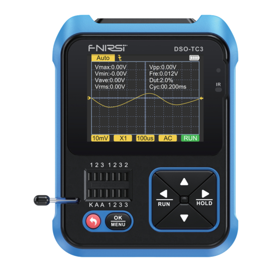
- Page 14 ●测量电容时显示的vLoss是损耗、 衰减的意思,这个值越大,电容性能越 差,越接近报废。 20pF以下的电容,经验做法是并一个20pF的电容测试。 ●测量电感的量程为10uH-1000mH,在电阻小于2.1kΩ时才进行电感测 量。 空心线圈和功率电感不能直接测电感,建议尝试串联合适的色环电 感测试。 ●测试座输出电流为6MA,需要更大电流驱动的可控硅。 ●LED检测为二极管,正向压降比正常值偏高。 双发光二极管检测为双二 极管。 检测同时发光二极管会闪亮。 K-A-A测试座说明 将被测元器件如稳压二极管的正极插入A、 负极插入K,锁紧插座后点 按 启动测试。 本仪器能测量的稳压管的最大范围为24V。 4.3 示波器操作及功能说明 Auto Vmax:0.00V Vpp:0.00V 在首页面短按左右键 、 切换到示 Vmin:-0.00V Fre:0.012V Vave:0.00V Dut:2.0% Vrms:0.00V Cyc:00.200ms 波器功能, 短按确认键 进入示波器 页面如图。 10mV 100us 屏幕底下和左上角的参数可以通过短按左右键 、...
- Page 15 ●1X/10X模式指示图标,这个必须和探头手柄上的1X/10X开关设置保持 一致,若探头是1X档,那么示波器也要设置为1X档,1X测量土40V电压, 10X测量土400V电压。 ●100uS为水平时基,表示水平方向一大格代表的时间长度。 ●AC/DC为输入耦合方式指示图标,AC表示交流耦合,DC表示直流耦合。 ●RUN/STOP为运行暂停指示图标,RUN表示运行,STOP表示暂停, 长按 左键切换。 实时测量参数 长按右键可以显示/隐藏在屏幕上半部分显示的8个实时测量参数: Vmax=最大电压 Vpp=峰峰电压 Vmin=最小电压 Fre=频率 Vave=平均值 Dut=占空比 Vrms=有效值电压 Cyc=周期 示波器探头 ●使用MCX插头的示波器探头插入顶面 【DSO】 插孔中,先调整好探头上 的衰减档,将探头的接地夹接到被测电路的 “参考地” 。 ●探头尖端或勾子稳妥接到电路的被测节点,在屏幕上观察被测点的电 压波形。 注意 ●探头衰减倍率应与被测信号电压相匹配,不可测量超过最大量程的 电压信号。 ●测量超过安全电压的信号时,人体不得碰触仪器的外露金属部分, 以免遭受电击。...
- Page 16 4.4 信号发生器操作及功能说明 信号发生器 在首页面短按左右键 、 切换到信 1.正弦波 2.方波 号发生器功能, 短按确认键 进入信号 3.脉冲波 4.三角波 频率: 0000 发生器页如图。 幅值: 3 . 3 V 5.斜坡 6.直流 共有6种信号波形可选择: ●正弦波 ●方波 ●脉冲波 ●锯齿波 ●三角波 ●直流 短按上下键 、 切换, 右键 可进入选择改变频率还是幅值, 再短 按右键 可改变数值, 短按左键 退出。 ( 频率上限为10000Hz, 幅 值上限为3.3V)...
- Page 17 ●电压检测: 需把MCX测试线插入顶端插孔 【IN (0~40V)】 中, 对测试线间 的电压进行检测。 ●DS18B20: 按屏幕提示将温度传感器插入测试座后进行测量。 ●DHT11: 按屏幕提示将温湿度传感器插入测试座后进行测量 (注意: DHT第三脚悬空不接) 。 ●红外解码: 在测试仪待测状态, 将红外遥控器对准测试仪面板上的 “IR" 标记, 按下遥控器按键, 仪器自动开始接收红外信号并进行解码处理, 解码成功后将显示用户码和数据码, 并显示对应的红外波形。 如果解码 失败或无法解码, 则不显示用户码和数据码, 此时如果在测试仪界面则 不能进入红外解码界面, 如果在红外解码界面则仍然显示上次成功的 解码信息。 ●自动校准: 按提示将三脚的短路线插入测试座的1-2-3插孔中,自动开始 校准,校准过程中根据提示断开短接线后,等进度条行进到100%便完成 了对本仪器当前模式的校准,无需进行其它操作。 注意 外部电路必须处于断电状态, 否则可能损坏仪器。 五、 设置菜单 设置页面 长按...
- Page 18 六、 固件升级 打开升级上位机软件, 电脑与设备之间USB线连接, 然后先下键 再按开 机键 进入升级页面, 最后在上位机页面选择相应的固件升级即完成固 件升级。 七、 常见问题解析 问: 如何判断电池是否充满? 答:电池充满后,充电指示灯会由红色变为绿色。 问: 为什么测试的波形左右晃动不停,无法固定? 答:需要调节触发电压,即右边的黄色箭头。 在触发模式下,按上下键调节 触发电压。 把黄色指示箭头调节到波形上下之间后,波形即可被触发以 及固定。 问: 为什么测一节电池或其他直流电压时没有波形? 答:电池电压信号是稳定直流信号,是没有曲线波形的。 在直流耦合模式下 调节垂直灵敏度,会出现一条往上或者往下的偏移直线的波形,如果是 交流耦合,则无论怎么调节都没有波形。 问: 为什么测量的市电220V波形并不是很标准的正弦波,有失真? 答:市电电网中一般都带有污染,含有较多的高次谐波成分,这些谐波叠加 在正弦波上就会表现出一个失真的正弦,属于正常现象。 一般市电波形 都是失真的,和示波器本身无关。 问: 为什么测量MOSFET、 IGBT得出的结果是二极管、 电容等参数? 答:由于MOSFET或IGBT的开启或关断电压大于5V(芯片最大供电电压)导 致MOSFET或IGBT无法正常开启或关断,所以只能测出它的等效参数。...
- Page 19 八、 注意事项 ●收到设备后,请在充满电后使用。 ●测量高压时,禁止碰触示波器任何金属部位,以免造成触电风险。 ●尽量不要在充电时,进行高压测试。 ●请勿将本机放置在不稳固或有可能受到强烈震动的地方。 ●请勿将本机放置在高湿度、 多尘、 阳光直射、 户外或接近热源的地方。 ●本仪器内置3.7V可充电锂电池供电,长时间使用时,请使用电源适配器 供电,延长电池使用寿命。 ●长时间不使用时,应将电池放电至3.7V后存放,且需每季度充放电循环 一次。 ●请使用说明书规格范围内的电压进行充电。 ●使用示波器模式的时候要注意档位的选择,示波器的档位跟探头的档 位要保持一致。 ●校准时,需要拔掉BNC探头,或者探头正负极短接。 九、 生产信息 产品名称: 三合一数字示波器 品牌/型号: 菲尼瑞斯/DOS-TC3 服务电话: 0755-83242477 生产商: 深圳市菲尼瑞斯科技有限公司 网址: www.fnirsi.cn 地址: 广东省深圳市龙华区大浪街道伟达工业园C栋西边8楼 执行标准: GB/T 15289-2013...
-
Page 20: Notice To User
●If there is any quality problem with the instrument or you have questions about it’ s use, you can contact FNIRSI online customer service or the manufacturer, we will promptly solve it for you. - Page 21 2.2 Specifications and parameters of the DSO Digital Oscilloscope ●The oscilloscope has a real-time sampling rate of 10MSa/s and a bandwidth of 500KHz. ●With complete trigger function (single, normal, automatic), no matter if you’ re using periodic analog signals or non-periodic digital signals. ●Maximum measured voltage signal is 400V.
- Page 22 2.3 Specifications and parameters of TC3 component test mode ●The instrument can automatically identify and measure various transistors, including NPN and PNP triodes, N-channel and P-channel mosfet, junction mosfet, diodes, dual diodes, thyristors, and resistors, inductors, capacitors and other passive components. ●...
- Page 23 Category Range Parameter Description 0.01Ω~50MΩ Resistor Resistance 10uH~1000mH Inductor Inductance value, DC resistance⑥ 0.1~4.5V Battery Voltage value, positive and negative polarity 0~40V Input voltage Voltage value 0-85℃ DS18B20 Temperature 0-60℃/5-95% DHT11 Humidity Infrared NEC protocol Display user code and data code, and display remote the corresponding infrared waveform.
- Page 24 Pulse wave 1-100KHz/3.3V/0-100% 1-10KHz/0-3.3V/50% Triangle wave 1-10KHz/0-3.3V/0-100% Ramp 0-3.3V 3. KEY INTERFACE ANALYSIS 3.1 Button Restoration Hide button Operation Function Reset Side hole...
- Page 25 Button Operation Function Short press Start up/Return Long press Short press Enter/confirm operation/remeasure Long press Enter system settings Move right/toggle Short press To turn off or on the parameter display when Long press displaying a waveform in oscilloscope mode. Move left/switch Short press Stop or run while displaying waveforms in Long press...
- Page 26 ●A total of five different test sockets are divided into 1-2-3 area and K-A-A area for the convenience of description(as pictured above). ●The test socket is at the bottom left of the screen, it is a 14-hole double-row socket with a locking device, and each socket is marked 1, 2, 3, K, A, those with the same label are short-circuited internally, and have the same function.
- Page 27 3.3 Signal interface Three MCX coaxial sockets are evenly distributed on the top surface, and their outer rings are connected together for a common ground, and they are used for different purposes: 【IN (0~40V)】 -Test voltage input port, the core wire is positive, the maximum measured voltage cannot exceed DC40V.
- Page 28 4.OPERATION and DESCRIPTION 4.1 Switching on and off 深圳市菲尼瑞斯科技有限公司 DSO-TC3 h t t p : / / w w w . f ni r s i . c n M-Tester There are four options on the home page, short press the left and right...
- Page 29 M-Tester Transistor(PNP) For triode measurement, short presst to start measurement. hFE=382 Vbe=0.79V IC=0.0mA M-Tester For reglulated diode measurement (Note: Zener reglulated diode is K-A-A socket, positive Vz = 24.0V and negative), short press to start measurement. 1-2-3 Zone Test Bench Instructions for Use Select an appropriate position in this area and jacks with different labels, and connect transistors, resistors, capacitors, inductances, etc.
- Page 30 ●The turn-on voltage of the thyristor must be less than 5V, in addition, the trigger current for maintaining conduction must be less than 6mA,Otherwise it cannot be measured correctly. ●The vLoss displayed when measuring capacitance means loss and attenuation. The larger the value, the worse the capacitance performance.For capacitors below 20pF, the rule of thumb is to test with a 20pF capacitor.
- Page 31 The parameters in the bottom and upper left corners of the screen can be selected by short pressing the left and right keys , and switching one by one after the effect is selected, and the up and down keys to switch or adjust;...
- Page 32 Real-time measurement parameters Long press the right button to show/hide the 8 real-time measure- ment parameters displayed in the upper part of the screen: Vmax=Maximum voltage Vpp=Peak-to-Peak voltage Vmin=Minimum voltage Fre=Frequency Vave=Average value Dut=Duty Vrms=RMS voltage Cyc=Cycle Oscilloscope probe ●Insert the oscilloscope probe with MCX plug into the [DSO] jack on the top surface, first adjust the attenuation gear on the probe, and connect the ground clip of the probe to the "reference ground"...
- Page 33 4.4 Operation and function description of the signal generator Generator On the home page, short press the left and 1.Sine right keys to switch to the signal 2.Square generator function, and short press the 3.Pulse confirmation key to enter the signal 4.Triangle 0000 Freq:...
- Page 34 There are 6 functions to choose from: ●Continuity test ●DHT11 temperature and humidity test ●Voltage test ●Infrared decoding ●DS18B20 digital temperature test ●Automatic calibration Short press the up and down , after switching to the corresponding function, it will automatically measure. ●Continuity test: Use any two corners of the jack 1, 2, and 3 of the test socket to conduct continuous resistance tests.
-
Page 35: Menu Setting
●Automatic calibration: Insert the three-pin short wire into the 1-2-3 jack of the test socket according to the prompts, and the calibration will start automatically. After disconnecting the short wires according to the prompts in the calibration process, wait until the progress bar reaches 100% to complete the calibration under the current mode of the instrument, no other operations are required. -
Page 36: Firmware Upgrade
6.FIRMWARE UPGRADE Open the upgrade software on the host computer, connect the computer and the device with a USB cable, then while pressing key, press the power key to enter the upgrade page. Finally select the corresponding firmware upgrade on the host computer page to complete the firmware upgrade. - Page 37 Q: Why are the parameters of diodes and capacitances obtained when measuring MOSFETs and IGBTs? Because the turn-on or turn-off voltage of the MOSFET or IGBT is greater than 5V (the maximum supply voltage of the chip), the MOSFET or IGBT cannot be turned on or off normally, so only its equivalent parameters can be measured.
- Page 38 9.Contact US Any FNIRSI'users with anyquestions who comes to contact us wiil have our promise to get asatisfactory solution + an Extra 6-Month Warranty to thanks for yoursupport! By the way, We have created an interesting community, welcome to contact FNIRSI staff...
- Page 40 下载用户手册&应用软件 Download User manual&APP&Software...
Need help?
Do you have a question about the DSO-TC3 and is the answer not in the manual?
Questions and answers