Advertisement
Quick Links
Advertisement

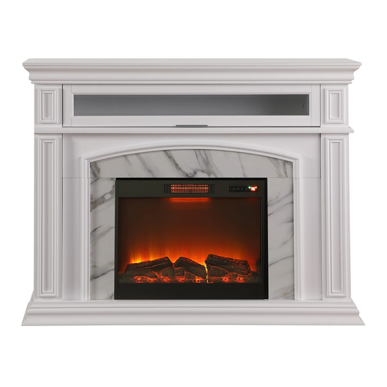
Summary of Contents for Broyhill CAL-622107
- Page 2 GENERAL BEST PRACTICES FOR ASSEMBLY: WARNINGS: To prevent serious injury or death, this product is equipped with a wall anchoring system. Before this product can be used, the wall anchoring system must be installed as directed in the assembly instructions.
-
Page 3: Care And Cleaning
CARE AND CLEANING: MAINTENANCE:... -
Page 4: Parts List
PARTS LIST: Top panel Side top left panel Side top right panel Front top left panel Front top right panel Middle panel Door panel Back plane Side bottom left panel Side bottom right panel Front bottom left panel Front bottom right panel Bottom frame baffle Bottom panel Front decorative panel... -
Page 5: Hardware List
HARDWARE LIST: Φ11*1-1/4" Bolts Spring washer Flat washer Cam-locks Φ7*5/8" Φ7*5/8" Φ6*1/2" Cam-bolts Screws Screws Screws Φ8*1/2" Hinges Hinges Handle Screws Φ6*5/8" Φ8*1-1/2" Screws Flat head screws Hook Anchor Plastic tie Allen wrench Fireplace insert Cam-tool... - Page 6 STEP 1 Attach 2 Structure Panel (18) to Side Bottom Left Panel (9) and Side Bottom Right Panel (10) as shown with 8 Bolt (A), 8 Spring Washer (B) and 8 Flat Washer (C).
- Page 7 STEP 2 Insert 3 Cam-bolt (E) to Front Bottom Left Panel (11) and Front Bottom Right Panel (12) as shown using Phillips screwdriver.
- Page 8 STEP 3 Align the Cam-bolts of Front Bottom Left Panel (11) with the holes in the edge of Side Bottom Left Panel (9) and slide the panels together. Insert 3 Cam-lock (D) into the holes of Side Bottom Left Panel and fully tighten to secure the panels together.
- Page 9 STEP 4 Attach Bottom Frame Baffle (13) and Bottom Panel (14) with 5 Bolt (A), 5 Spring Washer (B) and 5 Flat washer (C).
- Page 10 STEP 5 Attach Side Bottom Left Panel (9) and Side Bottom Right Panel (10) to Bottom Panel (14) as shown with 4 Bolts (A), 4 Spring Washer (B) and 4 Flat Washer (C).
- Page 11 STEP 6 Attach Left Decorative Panel (16) to Front Bottom Left Panel (11) and Bottom Panel (14) using Structure Panel (18), 4 Bolts (A), 4 Spring Washer (B) and 4 Flat Washer (C). Repeat process to attach Right Decorative Panel (17) to Front Bottom Right Panel (12) and Bottom Panel (14).
- Page 12 STEP 7 Insert 2 Cam-bolt (E) into Front Top Left Panel (4) and Front Top Right Panel (5) as shown and fully tighten using a Phillips screwdriver. -11-...
- Page 13 STEP 8 Align the Cam-bolts in Front Top Left Panel (4) with the holes in the edge of Side Top Left Panel (2) and slide the panels together. Insert 2 Cam-lock (D) into the holes of the Side Top Left Panel (2) and fully tighten to secure the panels together.
- Page 14 STEP 9 Place Top Panel (1) upside down on a soft smooth surface to avoid scratching the finish. Attach Side Top Left Panel (2) and Side Top Right Panel (3) to Top Panel (1) as shown with 4 Bolt (A), 4 Spring Washer (B) and 4 Flat Washer (C). -13-...
- Page 15 STEP 10 Attach Handle (K) to Door Panel (7) with 2 Screws (H). Attach 3 Hinge (I) to Door Panel (7) with 6 Screw (G). Attach Hinge (I) to Top Panel (1) with 12 Screws (G). Attach Hinge (J) to Door Panel (7) and Front Top Right Panel (5) with 4 Screw (M) as shown.
- Page 16 STEP 11 Align the holes in the Middle Panel (6) with the holes in the Front Top Panels and Side Top Panels. Secure Middle Panel (6) in place with 6 Bolt (A). With assistance, turn the assembled top upright and place on the assembled bottom as shown.
- Page 17 STEP 12 Attach Back Panel (8) to the assembled Mantel as shown with 12 Screw (F). Insert Fireplace Insert (S) into the front opening from the back. Ensure the Fireplace Insert is centered in the opening and secure it in place with 6 Screw (L). Attach 2 Hook (O) as shown with 4 Screw (F).
- Page 18 STEP 13 With assistance, carefully place the assembled mantle in the desired position against the wall. Mark where Hook (O) on the back of the fireplace meets the wall. Remove the assembled fireplace. Use one of the remaining Hooks (O) as a template and place it just below the marked locations on the wall marking the holes for the screws on the wall.


Need help?
Do you have a question about the CAL-622107 and is the answer not in the manual?
Questions and answers
How do you turn fireplace off without unplugging it?
Why is the mantle showing E1?