Advertisement
Introduction
Note:
The specific options are factory configured as per your order. Parts of this manual pertaining to other variants and options may not be applicable to your particular VISIONTEK GL-14 POS terminal.
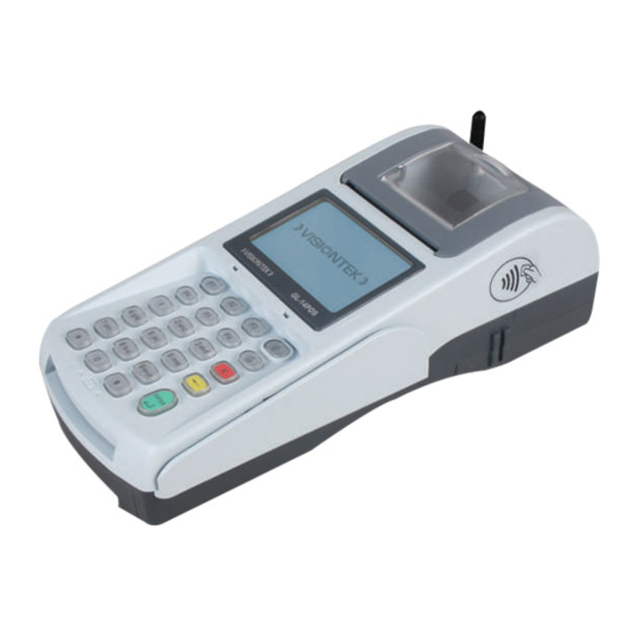
VISIONTEK GL-14 POS is a smart, compact multipurpose Transaction Terminal for on the go Handheld and Desktop applications.
The High speed Processor, large memory, built in optional GPRS / LAN / Wi-Fi Communication modules make the GL-14 a truly versatile unit suitable for use with multiple applications in a single Terminal

To protect yourself and your VISIONTEK GL-14 POS terminal against electrical shock, fire, power surges and other risks follow all pre-cautions while using.
INSTRUCTIONS AND CAUTIONS
- Never install the VISIONTEK GL-14 POS terminal in the following places:
- Exposed to direct sunlight, Moist, hot or dusty
- Unstable or vibrating places
- Near flammable liquid or gas
- Near large appliances Viz. A.C, Fridge etc.
- Near electric apparatus such as radios and TVs
- Near magnetic bodies such as audio speakers
- Avoid using the terminal during lightning storms
- Do not use liquid or aerosol cleaners for cleaning
- Do not disassemble or modify your GL-14 POS unit
- Do not open the cover of the GL-14 POS terminal during operation
- Do not expose the terminal to metal particles
- Do not yank the power cord or place anything on the power cord
- Do not pull the power plug with wet hands
- Do not try to charge the battery on other chargers
- Do not expose to the rain (or) water
Note:
Do not tamper or remove any stickers on the VISIONTEK GL-14 POS terminal.
It may void the warranty on the unit and weaken tamper detection.
CONTENTS OF SHIPPING CARTON
When you unpack the shipping carton, you should find:

- VISIONTEK GL-14 POS terminal with battery pack - Fig.1a
- Thermal Paper Roll - Fig.1b
- POS Console Cable - Fig.1c
- DC Adaptor - Fig.1d
- Stick Antenna - Fig.1e
Installation
HANDLING OF BATTERY PACK
Battery removal:
Pick up the unit and turn it bottom up to see the battery pack and Gently slide the cover towards bottom from the press area and remove the flap then take out the battery and remove the pin from the connectors.
Battery insertion:
Insert the connector to the Pin and place the battery pack to its place then gently slide the cover towards the top side.


-
Do not dispose the battery pack in fire.
-
Dispose used batteries in accordance with local recycling regulations.
-
Do not remove the battery while operation.
Handling of SIM
Pick up the unit and turn it bottom up to see the Communication cover.
Open the screws as shown in the Fig. 1

Slide out the cover to see the SIM slots as shown in the Fig. 2

SWITCHING ON THE UNIT
Power Switch
- The power ON/OFF switch is at rear right hand corner as shown in the figure below.
![]()
- To power up the terminal, press the ON/OFF switch and release.
- Hold the ON/OFF switch for 3 seconds to power off the terminal.

CONNECTING THE DC ADAPTOR
Insert the DC Adaptor's 9V DC output cable into the terminal's DC power connector socket.

Plug the DC power adaptor's mains power plug into a standard AC 100 - 240V, 50/60Hz DC output 9V, 2.2A.
Note
Even if the unit is not switched ON the battery pack in the unit will be charged when ever the DC Adaptor power is available
CONNECTING USB CLIENT
Insert the USB Client connector input pin into the USB Client port of the GL-14 POS terminal.

CONNECTING SERIAL INTERFACE
Insert the RJ45 cable end plug into the 8 pin socket marked "SERIAL".

CONNECTING ETHERNET
Insert the RJ45 cable end plug into the 8 pin RJ45 socket marked "Ethernet".

CONNECTING USB HOST
Insert the USB HOST connector into the 4 pin socket marked "USB_A "

STICK ANTENNA
High signal gain for GSM and CDMA

INSTRUCTIONS FOR PAPER ROLL COVER
DO
-
To Access printer roll simply lift the transparent latch.
![]()
-
For closing the printer cover simply press at two ends
![]()


DON'Ts
- While accessing the paper roll don't apply the pressure at "PRESSING AREA" otherwise printer roller will stuck to the printer and damage the whole paper roll assembly
![]()

LOADING THE THERMAL PAPER ROLL
- Unlock the printer cover, and then rotate the cover towards top side and open it.
- Place a roll of thermal paper (15 mtr.) in its housing as shown in the fig. below
![]()
- Hold the extreme end of the paper roll by keeping a few centimeters of thermal paper out of the paper roller of the printer cover, Ensure paper in its proper place and close the printer cover.
- Gently lock the printer cover

Operation
USING PAYMENT CARDS
Magnetic Swipe:
- Hold the card so that its magnetic stripe is facing down towards the Magnetic Swipe Card Reader.
- Swipe the card in a smooth continuous manner.
![]()

Smart Cards:
- Insert the smart card (Chip end first) into the opening provided for the reader on VISIONTEK GL-14 POS front panel as shown in the picture.
![]()
- For guidance, most smart cards will have directional guide arrows engraved or inscribed on the cards.
- In-built * Smart card reader and * Contactless card reader.
![]()


Precautions:
- Change/Charge the battery when it indicates one bar on LCD.
- For transactions, there should be a minimum of two bars present on the display.
* Indicates optional features.
Micro SD and SAM Cards:
Micro SD Card connector for expansion of memory and 2 SAM slots.
- Step Remove the battery pack
![]()
- Step Micro SD Card Slot
![]()
-
Step SAM Slots
![]()


TROUBLE SHOOTING
| Sl. No. | Problem | Remedy |
| | Nothing appears on the Display |
|
| | Printer not working |
|
SPECIFICATIONS
| Processor | ARM9 32-bit microprocessor @ 400MHz |
| Memory | 128 MB RAM (mDDR) / 256 MB Flash |
| Software | Linux 2.6 Operating System |
| Keypad | 23 keys (0 - 9 numeric keypad, *, #, 6 function keys, Power on/off, Back space, Paper feed, Cancel and Enter) |
| Printer | Thermal Graphic Printer with 15 meters Paper Roll |
| Display | Monochrome FSTN graphic LCD (128 x 64 pixels with icons) |
| Magnetic Stripe Card Reader | * Triple track (tracks 1,2,3) |
| Smart Card Readers | * Primary Smart Card Reader, ISO 7816 compliance Secondary Smart Card Reader |
| Contact less reader | * 14443 type NFC compliant Type A & Type B |
| Battery | Li-ion 7.4V, 1700 mAh |
* Indicates optional features.
NOTE
DO NOT THROW THE BATTERIES INTO THE DUST BINS, FIRE AND IN OPEN AREAS. PLEASE DISPOSE THEM IN ENVIRONMENT FRIENDLY MANNER.

VideosEVD 12E using VISIONTEK GL-14 POS Video
Documents / Resources
References
VISIONTEK in the Business of Transaction Terminals, Energy Meters, 3G Wireless and Software Products
Download manual
Here you can download full pdf version of manual, it may contain additional safety instructions, warranty information, FCC rules, etc.
Download VisionTek GL-14 POS - Point-of-Sale terminal Manual
Advertisement


Need help?
Do you have a question about the GL-14 POS and is the answer not in the manual?
Questions and answers