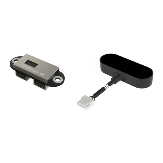
Summary of Contents for Nooploop TOFSense-M
- Page 1 TOFSense-M User Manual V1.4 Language: English Firmware: V1.0.6 NAssistant: V4.4.0 Product Series: TOFSense-M,TOFSense-M S...
-
Page 2: Table Of Contents
8.2.2 NLink_TOFSense_Read_Frame0 ............... 12 8.2.3 NLink_TOFSense_CAN_Frame0 ............... 12 8.2.4 NLink_TOFSense_CAN_Read_Frame0 .............13 9 FAQ ............................. 13 10 Reference ...........................16 11 Abbreviation and Acronyms ......................16 12 Update Log ..........................16 13 Further Information ........................16 Copyright © Nooploop LTd 2023. All Rights Reserved. Content... -
Page 3: Disclaimer
Nooploop product would cause severe personal injury or death. Nooploop customers using or selling Nooploop products in such a manner do so entirely at their own risk and agree to fully indemnify Nooploop and its representatives against any damages arising out of the use of Nooploop products in such safety-critical applications. - Page 4 According to GB 7247.1-2012 Safety of laser products - Part 1: Equipment classification and requirements, the maximum output laser power of the product is 50.5uW. Copyright © Nooploop LTd 2023. All Rights Reserved.
-
Page 5: Introduction
(15Hz for 8*8 mode, 60Hz for 4*4 mode), following the NLink_TOFSense_M_Frame0 protocol. Connect the TOFSense-M series products to NAssistant software using a USB to TTL module (refer to the datasheet for wire sequence and power supply voltage). After successful recognition, click to enter the settings page, and the UART active output mode configuration is shown in Figure 1. -
Page 6: Can Output
16 frames for 4*4 mode, each frame outputting ranging information for one pixel), following the NLink_TOFSense_CAN_Frame0 protocol. Connect the TOFSense-M series products to NAssistant software using a USB to TTL module (refer to the datasheet for wire sequence and power supply voltage). After successful recognition, click to enter the settings page, and the CAN active output mode configuration is shown in Figure 3. -
Page 7: Nassistant Operations
NLink_TOFSense _CAN_Frame0 protocol. Connect the TOFSense-M series products to NAssistant software using a USB to TTL module (refer to the datasheet for wire sequence and power supply voltage). After successful recognition, click to enter the settings page , and the CAN query output mode configuration is shown in Figure 4. -
Page 8: Record, Replay And Export
Note: If the folder is not automatically opened, find the corresponding folder according to the log prompt in the lower left corner of the software's main page, or click the menu button, click "Open Data Folder", and look for it in the "export_data" folder. Copyright © Nooploop LTd 2023. All Rights Reserved. -
Page 9: Pixel
Figure 6: Data recording, playback, and export. 5 Pixel The module supports 64 (8*8) and 16 (4*4) pixel output. The relationship between pixels and actual dimensions is shown in Figure 7. Figure 7: FOV and pixel correspondence schematic Copyright © Nooploop LTd 2023. All Rights Reserved. -
Page 10: Fov
Currently, the protocol verification is mainly based on the single-byte checksum at the end of the protocol frame. Example code: uint8_t verifyCheckSum(uint8_t *data, int32_t length){ uint8_t sum = 0; for(int32_t i=0;i<length-1;++i){ sum += data[i]; return sum == data[length-1]; Copyright © Nooploop LTd 2023. All Rights Reserved. -
Page 11: Example
… … … … … {uint24, dataindex{dis*1000,dis_s uint8, … … tatus,signal_strength} uint16} … … … … … {uint24, 90 65 00 26mm data63{dis*1000,dis_stat uint8, us,signal_strength} uint16} 3c 00 Reserved SumCheck uint8 0x7d Copyright © Nooploop LTd 2023. All Rights Reserved. -
Page 12: Nlink_Tofsense_Read_Frame0
Data Field signal_strength uint16 9f 00 index uint8 reserved uint8 … CRC Field CRC_delimiter ACK Slot ACK Field ACK_delimiter End Of Frame Dominant level Dominant or recessive level Recessive level Copyright © Nooploop LTd 2023. All Rights Reserved. -
Page 13: Nlink_Tofsense_Can_Read_Frame0
However, if two modules are at the same horizontal height and facing each other, the measurement may be affected for both of them. Q3. Why is there no data output from TOFSense-M? Each module has undergone strict testing before shipping. If there is no data, please first check if... - Page 14 Then enter the settings page through the upper computer and select UART mode to write parameters; TOFSense-M S can switch back to UART mode by sending the following serial command to the module several times: 54 20 00 ff 00 ff ff ff ff 00 ff ff 00 10 0e ff ff ff ff ff ff ff ff ff ff ff ff ff ff ff 7b Q7.
- Page 15 Q10.What is the reason for not being able to obtain data in CAN query mode? First, ensure that the wire sequence between CAN devices is correct. Secondly, the TOFSense-M series ports do not include 120R matching resistors. Ensure that the query device's side resistance...
-
Page 16: Reference
Expand the FAQ and optimize some descriptions 13 Further Information Company: SZ Nooploop Technology Co.,Ltd. Address: A2-207, Peihong building, No. 1, Kehui Road, Science Park community, Yuehai street, Nanshan District, Shenzhen E-amil: marketing@nooploop.com Website: www.nooploop.com Copyright © Nooploop LTd 2023. All Rights Reserved.


Need help?
Do you have a question about the TOFSense-M and is the answer not in the manual?
Questions and answers