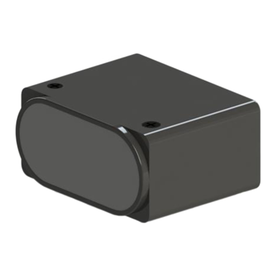
Summary of Contents for Nooploop TOFSense-F
- Page 1 TOFSense-F User Manual V1.2 Language: English Firmware: V1.1.8 NAssistant: V4.4.0 Product Series: TOFSense-F,TOFSense-F P...
-
Page 2: Table Of Contents
7.2.2 NLink_TOFSense_Read_Frame0 ................9 7.2.3 NLink_TOFSense_F_Setting_Frame0 ..............10 7.2.4 NLink_TOFSense_IIC_Frame0 ................11 8 FAQ .............................. 13 9 Reference ............................15 10 Abbreviation and Acronyms ...................... 15 11 Update Log ..........................15 12 Further Information ........................16 Content Copyright © Nooploop LTd 2023. All Rights Reserved. -
Page 3: Disclaimer
Nooploop product would cause severe personal injury or death. Nooploop customers using or selling Nooploop products in such a manner do so entirely at their own risk and agree to fully indemnify Nooploop and its representatives against any damages arising out of the use of Nooploop products in such safety-critical applications. -
Page 4: Introduction
Introduction 1 Introduction This document mainly introduces how to use the TOFSense-F and TOFSense-F P, as well as the precautions to be taken during use. You may need to refer to the following information for assistance in understanding: TOFSense-F_Datasheet.pdf ... -
Page 5: Iic Output
When the module is in UART mode (note that NAssistant cannot recognize modules in IIC mode), TOFSense-F series products can be connected to the NAssistant software via a USB to TTL module (referring to the data manual for wiring and power voltage). After successful identification, click to enter the setting page . -
Page 6: O Output
When the module is in UART mode (note that NAssistant cannot recognize modules in I/O mode), TOFSense-F series products can be connected to the NAssistant software via a USB to TTL module (referring to the data manual for wiring and power voltage). After successful identification, click to enter the setting page . -
Page 7: Nassistant Operations
NAssistant Operations Figure 4: I/O output mode configuration diagram For TOFSense-F/TOFSense-F P, the value range of Band_Start and Bandwidth is [0~15000] / [0~25000], with the unit of mm. Figure 5: Hysteresis comparison diagram 5 NAssistant Operations 5.1 Firmware Update At present, TOFSense-F/TOFSense-FP does not support firmware online upgrading. -
Page 8: Fov
NlinkUnpack sample analysis code developed in C language from the official website, which can effectively reduce the user's development cycle. Based on the data situation of TOFSense-F series products, in order to represent more data with fewer bytes, we use integers to represent floating-point numbers and transmit them through protocol frames. -
Page 9: Example
ID set to 0. To query data, send the following bytes from the host computer. If you need to query modules with different IDs, simply change the ID and checksum bytes accordingly. Raw data: 57 10 FF FF 00 FF FF 63 Copyright © Nooploop LTd 2023. All Rights Reserved. -
Page 10: Nlink_Tofsense_F_Setting_Frame0
[0,25000],unit:mm band width uint16 [0,25000],unit:mm reserved uint8 Reserved.The default value is 0xFF refresh rate uint16 Data refresh rata:1,2,5,10,25,50,100,200,350Hz filter factor uint8 Filter factor: 0~255.Default:5 reserved uint8 Reserved.The default value is 0xFF Copyright © Nooploop LTd 2023. All Rights Reserved. -
Page 11: Nlink_Tofsense_Iic_Frame0
[0-7] FOV.x : X direction FOV, unit: ° 0x18 [8-15] FOV.y : Y direction FOV, unit: ° [16-23] FOV.x_offest : FOV offset in the X direction, unit: ° [24-31] FOV.y_offest : FOV offset in the Y direction, unit: ° Copyright © Nooploop LTd 2023. All Rights Reserved. - Page 12 Slave Addr|W Reg Addr Stop Start Slave Addr|R Data[7:0] Data[7:0] Data[7:0] NACK Stop Start: Start signal W: Read flag 1 R: Write flag 0 ACK: Acknowledge NACK: Non-acknowledge Stop: Stop signal Host sends Copyright © Nooploop LTd 2023. All Rights Reserved.
-
Page 13: Faq
USB to TTL module's TX, RX, and GND to the corresponding pins of the TOF module, and temporarily not connect the VCC pin. Then plug the USB to TTL module into the computer. Copyright © Nooploop LTd 2023. All Rights Reserved. - Page 14 The data in the protocol frame is stored in little-endian mode, and it is multiplied by a certain multiple during encoding. For example, "ad 08 00" is first restored to hexadecimal data 0x0008ad, Copyright © Nooploop LTd 2023. All Rights Reserved.
-
Page 15: Reference
Version Firmware Version Data Description 1.0.5 20210918 Release first edition manual Added explanation of serial setting frame protocol 1.1.7 20220926 Optimized some descriptions 1.1.8 20230404 Optimized the description in the FAQ section Copyright © Nooploop LTd 2023. All Rights Reserved. -
Page 16: Further Information
Further Information 12 Further Information Company: SZ Nooploop Technology Co.,Ltd. Address: A2-207, Peihong building, No. 1, Kehui Road, Science Park community, Yuehai street, Nanshan District, Shenzhen E-amil: marketing@nooploop.com Website: www.nooploop.com Copyright © Nooploop LTd 2023. All Rights Reserved.


Need help?
Do you have a question about the TOFSense-F and is the answer not in the manual?
Questions and answers