Table of Contents
Advertisement
Quick Links
Distributed Monitoring System (DMS)
This document contains important
information about products that are
intended
Ex
explosive atmospheres.
VibroSmart DMS hardware manual MADMS-HW/E
Edition 3
- September 2015
HARDWARE MANUAL
VibroSmart®
for
use
in
potentially
Title page
Meggitt SA
Route de Moncor 4
PO Box 1616
CH - 1701 Fribourg
Switzerland
www.meggittsensingsystems.com
www.vibro-meter.com
Advertisement
Table of Contents

Related Manuals for Meggitt VibroSmart VSA301


Summary of Contents for Meggitt VibroSmart VSA301
- Page 1 Title page HARDWARE MANUAL VibroSmart® Distributed Monitoring System (DMS) Meggitt SA Route de Moncor 4 This document contains important PO Box 1616 information about products that are CH - 1701 Fribourg intended potentially Switzerland explosive atmospheres. VibroSmart DMS hardware manual MADMS-HW/E www.meggittsensingsystems.com...
-
Page 2: Revision Record Sheet
REVISION RECORD SHEET Date Written by / Edition Description Signature of issue modified by 25.08.2014 P. Ward Original edition. Removed all references to the VSV310 vibration monitoring module (deprecated), the VSR020 relay module (under development) and the embedded/plug-in signal conditioners (under development). - Page 3 Document released by Technical Publications P. Ward 24.09.2015 The duly signed master copy of this page is stored by the Technical Publications Department of Meggitt SA and can be obtained by writing to Technical Publications. VibroSmart DMS hardware manual MADMS-HW/E Edition 3...
-
Page 4: Copyright
Meggitt Sensing Systems are based on information believed to be reliable, but unless otherwise expressly agreed in writing with Meggitt SA the accuracy or completeness of such data is not guaranteed. Before using this product, you must evaluate it and determine if it is suitable for your intended application. Unless otherwise expressly agreed in writing with Meggitt SA, you assume all risks and liability associated with such use. -
Page 5: Preface
The Meggitt Sensing Systems facility in Fribourg, Switzerland was formerly known as Vibro-Meter SA, but is now Meggitt SA. This site produces a wide range of vibration and dynamic pressure sensors capable of operation in extreme environments, leading-edge microwave sensors, electronics monitoring systems and innovative software for aerospace and land-based turbo-machinery. - Page 6 Not all possibilities are described in this manual. Nevertheless, several specific configurations are described in detail. These can often be adapted to specific applications. When in doubt, contact Meggitt Sensing Systems so that an optimum measurement solution can be determined.
- Page 7 Abbreviations and glossary The following table defines some useful abbreviations and terms found in this manual. Term Definition Alarm bypass, a DSI input signal +24 V power supply with a 3 A output, suitable for use in a VibroSmart DMS APF 196 +24 V power supply with a 5 A output, suitable for use in a VibroSmart DMS...
- Page 8 VibroSmart is the name of a family of modular and scalable modules and products, VibroSmart® from Meggitt Sensing Systems’ Vibro-Meter product line, that can be assembled and configured to create a distributed monitoring system The VibroSight total monitoring solution, from Meggitt Sensing Systems’ Vibro-Meter product line, is a highly integrated software suite that supports the effective condition VibroSight®...
-
Page 9: Safety
SAFETY Symbols and styles used in this manual SAFETY Symbols and styles used in this manual The following symbols are used in this manual where appropriate: The WARNING safety symbol HIS INTRODUCES DIRECTIVES PROCEDURES OR PRECAUTIONARY MEASURES WHICH MUST BE EXECUTED OR FOLLOWED AILURE TO OBEY A WARNING CAN RESULT IN INJURY TO THE OPERATOR OR THIRD PARTIES The CAUTION safety symbol... - Page 10 Safety procedures should be communicated to all personnel who may operate any piece of equipment described in this manual. Meggitt Sensing Systems does not accept any liability for injury or material damage caused by failure to obey any safety-related instruction or due to any modification, transformation or repair carried out on the equipment without written permission from Meggitt SA.
- Page 11 General handling precautions In general, Meggitt Sensing Systems’ products are rugged devices which can withstand a certain amount of careless handling. Nevertheless, certain precautions should be taken when handling this equipment. Read the following recommendations carefully before handling devices. •...
- Page 12 THIS PAGE INTENTIONALLY LEFT BLANK VibroSmart DMS hardware manual MADMS-HW/E Edition 3 - September 2015...
-
Page 13: Table Of Contents
TABLE OF CONTENTS TABLE OF CONTENTS TITLE PAGE ............. . . i REVISION RECORD SHEET . -
Page 14: Table Of Contents
TABLE OF CONTENTS 2.2.2.3 VibroSmart DMS signal conditioning (VSV300) ... . 2-5 2.2.2.4 VibroSmart DMS communications adaptors (VSI010) ..2-5 2.2.3 VibroSmart devices ......... . . 2-5 DIN rail . - Page 15 TABLE OF CONTENTS Discrete signal interface (DSI) control inputs ......3-9 3.6.1 DSI Master and discrete signal interface (DSI) signal sharing .
- Page 16 TABLE OF CONTENTS Mounting a VibroSmart VSN010 real-time Ethernet switch on a DIN rail ..4-8 Removing a VibroSmart VSN010 real-time Ethernet switch from a DIN rail ..4-8 5 VIBROSMART DMS NETWORKING .
- Page 17 TABLE OF CONTENTS 7 VSV300 VIBRATION MONITORING MODULE....... . 7-1 Introduction .
- Page 18 TABLE OF CONTENTS Operating modes ..........7-18 Configuration .
- Page 19 TABLE OF CONTENTS Overview of operation ..........9-4 9.4.1 Short-distance signal transmission using one VSA301 .
- Page 20 TABLE OF CONTENTS 10.7 Outputs ............10-11 10.7.1 VSI010 logical functions .
- Page 21 TABLE OF CONTENTS 12 VSN010 REAL-TIME ETHERNET SWITCH ....... . . 12-1 12.1 Introduction .
- Page 22 TABLE OF CONTENTS 13.5 Installation procedure for VibroSmart DMS modules ..... . 13-5 13.5.1 First-time installation of a VibroSmart DMS ..... . . 13-6 13.5.2 Subsequent installation of VibroSmart devices.
- Page 23 16.1 VibroSmart VSA301 connectors ........
- Page 24 TABLE OF CONTENTS 19 CUSTOMER SUPPORT ..........19-1 19.1 Contacting us .
-
Page 25: Introduction
(ATEX Zone 2), high temperatures (70°C) and high mechanical stress. VibroSmart complements the VM600 series of rack-based solutions from Meggitt Sensing Systems’ Vibro-Meter ® product line and is compatible with the same VibroSight ® software. -
Page 26: Safety-Related Systems
Safety of Electrical/Electronic/Programmable Electronic Safety-related Systems” and includes support for PROFIsafe, making it suitable for use in safety-related applications. Contact Meggitt Sensing Systems for additional information. 1.3.2 Ex-related systems The VibroSmart DMS products in this manual are approved for use in hazardous locations (that is, potentially explosive atmospheres), as described in the Ex certificates for the product. - Page 27 Other VibroSight devices – such as the VSN010 real-timer Ethernet switch – mount directly on a DIN rail (that is, they are complete, include all of the I/O connections required and do not require a terminal base). For the VSI010 communications interface module, a range of communications adaptors are available that plug into the associated VSB010 module’s terminal base in order to interface with various industry standard fieldbuses.
- Page 28 From front-end measurement VSV300 / VSB010 chain vibration (sensors and/or +24 V monitoring signal module power conditioners) supply rail Power supply Ethernet cabling cabling Computer with network adapter (NIC) Figure 1-1: Basic VibroSmart DMS – example with a single stand-alone module. In more advanced configurations, typically used for machinery protection and/or condition monitoring applications, a VibroSmart DMS consists of one or more of the following system components:...
-
Page 29: Vibrosmart Dms Hardware
2 Overview of VibroSmart DMS hardware for a list of the VibroSmart modules and devices available from Meggitt Sensing Systems for use in a VibroSmart DMS. Typically, all of the VibroSmart DMS devices that make up a VibroSmart DMS are mounted on an industry standard DIN rail. -
Page 30: Vibrosight Software
1.4.2 VibroSight software The VibroSight® software, from Meggitt Sensing Systems’ Vibro-Meter® product line, is a common software platform from Meggitt Sensing Systems for use with all of its energy market products, including VibroSmart DMS hardware (modules and devices) and VM600 rack hardware (cards). -
Page 31: Communicating With A Vibrosmart Dms
This edition of the VibroSight software is suitable for machinery protection NOTE: systems and is the equivalent of the VM600 MPS1 software used with VM600 rack-based machinery protection systems from Meggitt Sensing Systems. • Standard edition The Standard edition is the fully featured edition with full system capabilities. It is capable of handling live and historical data for both static and dynamic measurements. - Page 32 The VibroSight total monitoring solution software can be used as follows: • VibroSight System Manager is required to configure and manage a VibroSmart DMS. For example, it is used to configure IP addresses and NTP server addresses, identify/locate VibroSmart DMS devices and upgrade firmware. •...
- Page 33 Client application software modules Base application Application packages (optional) package (included) Combustion Configurator Event Mimic Hydro air-gap VibroSight monitoring Viewer monitoring (vibration) (XMC16) Tape recorder Scope System Vision data Manager (XMx16) “server connection” External interfaces (optional) Server software module Modbus client and client and server...
-
Page 34: System Size Considerations
1.6 System size considerations 1.6.1 VibroSmart DMS modules One to sixteen VibroSmart modules can exist in a measurement block (numbered 0 to 15 in the VibroSight software). And one to eight VibroSmart modules can exist in a DMS (numbered 0 to 7 in the VibroSight software). Therefore, a maximum of 128 modules can exist in a VibroSmart DMS. - Page 35 • “Local” refers to a signal (input or output) that has its source within the immediate environment where it is used (for example, within a module). For example, a local relay is a relay integrated in the VibroSmart DMS module and a local DSI input or a local tacho is a signal that is connected to the terminal base of the VibroSmart DMS module.
- Page 36 THIS PAGE INTENTIONALLY LEFT BLANK VibroSmart DMS hardware manual MADMS-HW/E Edition 3 - September 2015...
-
Page 37: Overview Of Vibrosmart Dms Hardware
2 OVERVIEW OF VIBROSMART DMS HARDWARE This section provides a brief overview of the hardware used in a VibroSmart DMS, including the physical appearance of the VibroSmart devices and basic functional information. More detailed information on a particular VibroSmart device can be found in its dedicated chapter. Further information on specific elements can be found in the corresponding NOTE: VibroSmart DMS data sheets. -
Page 38: Vibrosmart Dms Hardware
2.2 VibroSmart DMS hardware VibroSmart DMS hardware includes: • VibroSmart modules that consist of an electronics module and an associated terminal base. • VibroSmart devices that are self-contained and complete (that is, no terminal bases are required). A VibroSmart DMS module consists of an electronics module (providing configurable machinery monitoring functions) that clips into a VibroSmart terminal base, which mounts on a DIN rail. -
Page 39: Vibrosmart Dms Terminal Bases
2.2.2 VibroSmart DMS terminal bases VibroSmart terminal bases incorporate embedded buses and provide all of the I/O connections required to interface to a module. Terminal bases also include memory to store the configuration of the attached module, which allows modules to be hot-swapped. Modules and terminal bases use mechanical keycoding for a system that is simple to operate and use. - Page 40 Eth2 Eth1 (left) (right) Orange Green Green Orange Figure 2-2: VibroSmart terminal base LEDs Table 2-1: Status indicator operation for the VibroSmart DMS terminal base LED state Description The left (orange) Ethernet (RJ45) LED indicates the speed of the connection Left No link speed established (orange)
-
Page 41: Vibrosmart Dms Module And Terminal Base Compatibility
2.2.2.2 VibroSmart DMS module and terminal base compatibility The compatibility between VibroSmart DMS modules and terminal bases is given in Table 2-2. Table 2-2: VibroSmart DMS module and terminal base compatibility VibroSmart DMS VibroSmart DMS Notes module terminal base VSI010 VSB010 VSV300 VSB300... -
Page 42: Din Rail
• Power supplies (+24V • APF 196 AC-DC converter with 3 A output. • APF 197 AC-DC converter with 5 A output. • APF 198 AC-DC converter with 7.5 A output. • APF 200 AC-DC converter with 3.75 A output and Ex approval for use in hazardous locations (potentially explosive atmospheres). -
Page 43: Vibrosmart Measurement Modules
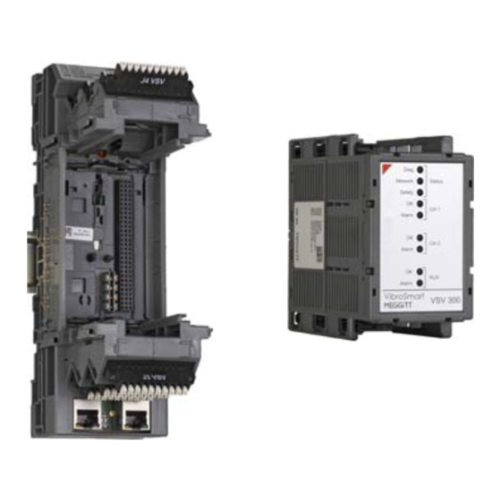
2.4 VibroSmart measurement modules The following different types of VibroSmart DMS measurement module are available: • VSV300 vibration monitoring module 2.4.1 VSV300 vibration monitoring module The VibroSmart VSV300 is a vibration monitoring module with two independent dynamic vibration channels and one auxiliary channel, that can be configured as either a tachometer or a DC input channel. - Page 44 Table 2-3: LED behaviour for the VSV300 module Monitoring LED state VSV300 module status Description status The Diag (Status) LED indicates the status of the VSV300 module, such as normal operation, configuration status or internal hardware or firmware failures Not powered or external power supply out of No power supply Not running normal range...
- Page 45 Table 2-3: LED behaviour for the VSV300 module (continued) Monitoring LED state VSV300 module status Description status The Safety (Status) LED indicates the status of the VSV300 module’s safety function and any active adaptive monitoring functions (AB or TM) Normal operation of Safety function operating normally (without Green Running...
-
Page 46: Vsb300 Terminal Base
A failure of safety function is indicated by: • The Safety (Status) LED on the front panel of the module blinking red. • VibroSight System Manager displaying the operating mode of the module as Fail-safe. When a failure on safety function occurs, the operating mode of the module will switch from Operational to Fail-safe and user intervention is required. -
Page 47: Vibrosmart Communications Modules
2.5 VibroSmart communications modules The following different types of VibroSmart DMS communications module are available: • VSI010 communications interface module. 2.5.1 VSI010 communications interface module The VibroSmart VSI010 communications interface module is an optional communications module for use with other VibroSmart modules in a DMS. The VSI010 module acts as a highly configurable data communications bridge, with support for up to two industry standard fieldbuses. - Page 48 Table 2-4: LED behaviour for the VSI010 module Monitoring LED state VSI010 module status Description status The Diag (Status) LED indicates the status of the VSI010 module, such as normal operation, configuration status or internal hardware or firmware failures Not powered or external power supply out of No power supply Not running normal range...
- Page 49 Table 2-4: LED behaviour for the VSI010 module (continued) Monitoring LED state VSI010 module status Description status The Safety (Status) LED indicates the status of the module’s safety function and any active adaptive monitoring functions (AB or TM) Normal operation of Safety function operating normally (without Green Running...
-
Page 50: Vsb010 Terminal Base
When a failure on safety function occurs, the operating mode of the module will switch from Operational to Fail-safe and user intervention is required. The module must be restarted, either by the switching the power supply to the module off and then on, or by removing the module from its terminal base and then re-inserting the module. - Page 51 Figure 2-6: VSN010 front panel The behaviour of the VSN010’s LEDs is explained in Table 2-5. Table 2-5: LED behaviour for the VSN010 LED state VSN010 module status Description The Power LED indicates the status of the VSN010 Ethernet switch’s power supplies (input and internal) No power supply Not powered or power supply is out of normal range Power...
-
Page 52: Vsa301 Buffered Output Amplifier
VSN010 2.6.2 VSA301 buffered output amplifier The VibroSmart VSA301 is an amplifier designed specifically for operation with the buffered transducer outputs from a VibroSmart VSV300 vibration monitoring module. A VSA301 is used with a VSV300 in order to amplify the VSV300’s buffered transducer “raw”... -
Page 53: Vsa301 Front Panel
2.6.2.1 VSA301 front panel The front panel for a VSA301 is shown in Figure 2-6. Figure 2-7: VSA301 front panel The behaviour of the VSA301’s LED is explained in Table 2-5. Table 2-6: LED behaviour for the VSA301 device LED state VSN010 module status Description The Power LED indicates the status of the device’s power supplies (input and internal) -
Page 54: Apf 196, Apf 197 And Apf 198 Power Supplies
2.6.3 APF 196, APF 197 and APF 198 power supplies The APF 196, APF 197 and APF 198 are power supplies that can be used to power VibroSmart DMS devices or any other equipment requiring a 24 V power supply. These are AC-DC converters intended for use with an AC mains supply (85 to 264 V ) or a high-voltage DC supply (80 to 370 V... -
Page 55: Apf 196, Apf 197 And Apf 198 Front Panels
Table 2-7: APF 196, APF 197 and APF 198 power supplies Nominal outputs Power supply Output connector Voltage Current Power 4-contact connector: 24 V APF 196 70 W 2x 24 V and 2x GND 5-contact connector: 24 V APF 197 120 W 2x 24 V and 3x GND... -
Page 56: Apf 200 And Apf 201 Power Supplies
2.6.4 APF 200 and APF 201 power supplies The APF 200 and APF 201 are power supplies that can be used to power VibroSmart DMS devices or any other equipment requiring a 24 V power supply. They are AC-DC converters intended for use with an AC mains supply (85 to 264 V For a VibroSmart DMS, the maximum power rating of a power supply must be <200 W, in order to help ensure electrical safety. -
Page 57: Apf 200 And Apf 201 Front Panels
Table 2-8: APF 200 and APF 201 power supplies Nominal outputs Power supply Output connector Voltage Current Power 5-contact connector: 1x 24 V and 1x GND, 24 V APF 200 3.75 A 90 W 1x voltage output signal and 2x relay contacts for the DC OK indicator 7-contact connector: 2x 24 V... -
Page 58: Industrial Housings
(NEMA/IP rated enclosures) with ratings up to IP56 or equivalent are available. These housings contain DIN rails suitable for housing multiple VibroSmart DMS modules. For further information on these enclosures, contact your nearest Meggitt Sensing Systems representative. VibroSmart DMS hardware manual MADMS-HW/E... -
Page 59: Vibrosmart Dms Features And System Elements
3 VIBROSMART DMS FEATURES AND SYSTEM ELEMENTS The VibroSmart DMS includes features and system elements that enable distributed machinery monitoring systems that are easy to create and maintain. This includes: • A system bus (SBUS) that supports real-time and non-real-time Ethernet communications. - Page 60 The SBUS supports data transfer rates of 100 Mbps (100BASE-TX, IEEE 802.3) at distances up to 100 m, with a maximum VibroSmart DMS network size (length) of 700 m (see 5 VibroSmart DMS networking). It ensures the transfer of both real-time (time critical) and non-real-time (standard) information between VibroSmart modules, and supports communication with the computer running the VibroSight software.
-
Page 61: Vibrosmart Dms Device Ethernet Ports And Connectors
It is the SBUS, selectable Ethernet connectors, and VSN010 real-time Ethernet switch that allow different physical networks of VibroSmart DMS modules and devices to be created to meet the requirements of different machinery monitoring applications. See 3.2 VibroSmart DMS device Ethernet ports and connectors 5 VibroSmart DMS networking for additional information. -
Page 62: Sidebus Connectors
The selection of the Ethernet connector (sidebus or Ethernet) to be used for each side of a VibroSmart DMS module has implications for how the modules are installed. 3.2.1.1 Sidebus connectors The sidebus connectors, J10 (right) and J11 (left), are proprietary connectors that allow direct connections between VibroSmart DMS modules that are located side-by-side (that is, adjacent to each other). - Page 63 More specifically, a measurement block is a logical grouping of VibroSmart DMS NOTE: modules that is created and configured using the VibroSight Configurator software. At its most basic, a VibroSmart DMS consists of one or more measurement blocks and an optional computer running the VibroSight software.
-
Page 64: Vibrosmart Dms Device Configuration
communicate the missing module’s terminal base (see Live removal and insertion of VibroSmart DMS modules (“hot-swapping” capability)). 3.4 VibroSmart DMS device configuration Being fully software configurable, the VibroSmart DMS devices store their configuration in non-volatile memory so that it is kept, even when the power supply to the device is turned off. For VibroSmart DMS products that consist of a module that clips into an associated terminal base, the module’s configuration is stored in non-volatile memory on the terminal base. - Page 65 When an individual module is replaced (“hot-swapped”) in a powered DMS, the replacement module will automatically: Loads its configuration from terminal base (which stores the configuration of the module being replaced). Perform a brief re-initialisation and self-check (see 3.12 Operating modes).
- Page 66 (VibroSmart DMS module removed) Computer running the VibroSight software VibroSmart VibroSmart DMS module DMS module (Border device) (a) Hot swapping a VibroSmart DMS module – module to module communications and module to VibroSight communications continue (VibroSmart DMS module removed) Computer running the VibroSight software...
-
Page 67: Live Removal And Insertion ("Hot-Swapping") In Potentially Explosive Atmospheres
3.6 Discrete signal interface (DSI) control inputs The VibroSmart DMS implements the discrete signal interface (DSI) that is also used by the VM600 rack-based machinery protection systems from Meggitt Sensing Systems. VibroSmart DMS modules implement up to four discrete control signal inputs that can be used to control the operation of an individual module in response to external system signals: •... -
Page 68: Dsi Master And Discrete Signal Interface (Dsi) Signal Sharing
When a VSI010 communications interface module is used in a measurement block, the DSI signals of the VSV300 vibration monitoring modules in the same measurement block as the VSI010 module are available as status bits that can be used as inputs to the basic logical functions of the VSI010 (see 3.8 Logical functions). -
Page 69: Tacho Signal Sharing
SBUS (Ethernet) Trigger message DSI command Trigger message DSI command Trigger message (real-time) (non-real-time) (real-time) (non-real-time) (real-time) DSI master DSI master (multiplexer) (multiplexer) DSI-based DSI-based processing processing DSI input DSI input VibroSmart VibroSmart (J1 connector) (J1 connector) DMS module DMS module External External configured as... - Page 70 SBUS Tacho message Tacho message Tacho message Tacho message (real-time) (real-time) (real-time) (real-time) CH1 tacho CH1 tacho selection selection processing processing processing processing CH2 tacho CH2 tacho selection selection AUX (tacho) AUX (DC) processing processing VSV300 module VSV300 module generating and using using a “local”...
-
Page 71: Logical Functions
or a “remote” tacho as appropriate. This is done at the input channel and processing block node levels. Tacho signal sharing is typically used to allow different processing blocks on different VSV300 modules to use the same tacho signal as a reference speed, that is, the tacho signal is used for phase synchronisation of the machinery data. -
Page 72: Relay Switching Capacity In Potentially Explosive Atmospheres
A relay is driven by a single input signal that is local to the module itself. See 7.6.4 VSV300 relays 10.7.2 VSI010 relays for further information. In addition, a relay must be configured as: • Normally De-energized (NDE) or Normally Energized (NE) For relays configured as Normally De-energized (NDE), the control input to the relay’s coil is off by default so there is a closed circuit between the NC and COM contacts (and an open circuit between the NO and COM contacts) for a normal condition. -
Page 73: Operation Of Relays
latched or not latched. It also depends on the control signal that is used to drive the relay. For example, status information for an input channel (Sensor OK Check), an alarm bit (Danger+, Alert+, Alert−, Danger−) or a logical function’s output. 3.9.3 Operation of relays A relay can be configured to be either normally de-energised (NDE) or normally energised (NE). -
Page 74: Grounding Concept
3.10.1 Grounding concept The sensor interface for a VibroSmart DMS measurement module varies, depending on the type of sensor. However, the concept of isolating the case of the signal conditioner from the ground (electrical common) is common to all sensor interfaces. This is illustrated in Figure 3-6 for a piezoelectric sensor. -
Page 75: Vibrosmart Dms Global Time Synchronisation
At the same time, a second module in the VibroSmart DMS measurement block is automatically elected as the “backup” PTP master module. If the “main” PTP master becomes unavailable, the modules in the measurement block will immediately switch to the “backup” PTP master, which effectively becomes the new “main”... -
Page 76: Ntp
calculated by the VibroSight Server using its server time, each module’s time and the known deltas to each measurement block. All data (card and external interface) is stored in the VibroSight Server database NOTE: using timestamps generated by the VibroSight Server. Accordingly, a VibroSmart DMS can be deployed in one of two ways: either without or with an NTP server. -
Page 77: Vibrosmart Dms Without An Ntp Server (Ntp-Free)
3.11.3.2 VibroSmart DMS without an NTP server (NTP-free) Deployment and operation of a VibroSmart DMS without an NTP server (NTP-free) is the default mode of operation, that is, the use of an NTP server is disabled by default. This is recommended for the vast majority of machinery monitoring applications that typically work with long-term historical trends. -
Page 78: Power-On Self Test
Therefore, the startup time of a VibroSmart DMS is approximately 5 minutes (the startup time of the slowest device). The operating modes of a VibroSmart DMS device are available as information in VibroSight System Manager. For example, VibroSight System Manager displays Operational as the operating mode for a VibroSmart DMS device during normal operation but enters Fail-safe when there is a failure on safety function. - Page 79 Table 3-1: VibroSmart DMS device operating modes Displayed VibroSmart DMS device VSI010 VSN010 VSV300 Device outputs VibroSight Description operating mode System Manager Selected after the power on or reset of the device. In the Bootstrap mode, the Bootstrap √ √ √...
- Page 80 Table 3-1: VibroSmart DMS device operating modes (continued) Displayed VibroSmart DMS device VSI010 VSN010 VSV300 Device outputs VibroSight Description operating mode System Manager The Fail-safe mode is selected permanently when a hardware failure is detected by a module’s built-in self test (BIST). In this mode, the module VSI010 and VSV300: switched its relays to the safe...
-
Page 81: Power Supplies
3.13Power supplies 3.13.1 Device power supply (input) VibroSmart DMS devices require a +24 V power supply (+16 to +32 V input range). The total power consumption of all the DMS devices that will be used in a DMS should be calculated to ensure that an adequate power supply is used. -
Page 82: Zero-Configuration Networking
3.14Zero-configuration networking The VibroSmart DMS and the VibroSight software and use a proprietary implementation of the zero configuration networking (zeroconf) protocols for all required networking operations. This includes the automatic discovery of and communications between VibroSight-system components, such as VibroSmart DMS devices and the VibroSight software. The use of zeroconf allows a functioning network to automatically created without requiring either user intervention (to set up devices, IP addresses and so on) or special configuration servers. -
Page 83: Assembling And Mounting Vibrosmart Dms Devices
4 ASSEMBLING AND MOUNTING VIBROSMART DMS DEVICES This section provides more detailed information on the terminal bases used by VibroSmart DMS modules and an overview of the assembly (and disassembly) of VibroSmart DMS modules and terminal bases, and DIN rail mounting (and removal). It also includes an overview of the DIN rail mounting (and removal) of other VibroSmart DMS devices that do not use a terminal base. -
Page 84: Terminal Base Front Panel
Terminal bases provide the connections and mechanical key coding for interfacing with the VibroSmart DMS modules – which are hot-pluggable (that is, the modules can be replaced without turning off the power supply to the terminal base).Terminal bases support embedded buses, auto-detection and auto-configuration, resulting in a system that is simple to operate and use. -
Page 85: Terminal Base Dip Switch
When turned 90° clockwise to the right limit, the claws of the terminal base’s DIN rail adaptor close (move towards one another) to grip the DIN rail. The release handles used for separating a VibroSmart DMS module from a terminal base are located above and below the front panel on the left of the module’s body. - Page 86 The Ethernet connectors (Eth1 and Eth2) can be used for communication between a computer running the VibroSight software and a DMS module or for communication between VibroSmart DMS modules that are located some distance from each other. The sidebus connectors (J10 and J11) can be used for communication between adjacent VibroSmart DMS to reduce installation complexity and cost.
-
Page 87: Terminal Base Rear Panel
During normal operation, the DIP switch settings are constantly monitored by the VibroSmart DMS module. When the DIP switch settings change, the physical routing of the SBUS (Ethernet) signals via the Ethernet or sidebus connectors changes immediately (that is, there is no requirement to turn the power to the module off and then on). -
Page 88: Mounting A Single Vibrosmart Dms Terminal Base On A Din Rail
Prerequisites The VibroSmart DMS modules release handles (located top and bottom on the left of the module’s body) are retracted, that is, level with the front panel of the VibroSmart DMS module. Procedure Simultaneously push both of the VibroSmart DMS modules release handles towards the terminal base using the force necessary to overcome the mechanical locking mechanism and the friction of the connectors. - Page 89 The new terminal base mounted adjacent to an existing terminal base slides into the body of the existing terminal base at the same time as mounting on the DIN rail using its DIN rail adaptor. Mounting VibroSmart DMS modules side-by-side reduces external wiring NOTE: requirements as the J1x connectors distribute the SBUS and the power supply.
-
Page 90: Removing A Vibrosmart Dms Terminal Base From A Din Rail
Use the Torx driver to rotate the DIN rail adaptor screw clockwise so that the claws move towards one another, then hook over and grip the DIN rail – looking at the terminal base from the side, the claws should extend 3 mm (approx.) from the body of the terminal base. -
Page 91: Vibrosmart Dms Networking
5 VIBROSMART DMS NETWORKING 5.1 Introduction A VibroSmart DMS can be deployed using different network topologies depending on the requirements of the machinery monitoring application. The simplest VibroSmart DMS consists of a single VibroSmart DMS module and a power supply that implement a machinery protection system. Such systems are often deployed in a “stand-alone”... -
Page 92: Vibrosmart Dms Networking
VibroSmart modules mounted separate from one another cannot use the sidebus connectors for Ethernet (SBUS) communications, so external network cabling is required for each VibroSmart module. Mounting modules separately from one another allows individual VibroSight modules to be installed closer to where they are actually required, which reduces costs by minimising expensive measurement chain cabling. -
Page 93: Network Cabling
A linear network topology is created by connecting each VibroSmart DMS module in series to the next (see 5.5 VibroSmart DMS linear networks). In a VibroSmart DMS linear network, the VibroSmart DMS modules acts as DANHs and propagate network traffic from one Ethernet port to the other, along all of the modules on the network. -
Page 94: Vibrosmart Dms Point-To-Point Networks
• For cable lengths (network segments) less than 50 m • Category 5 enhanced (Cat 5e) cable of type SF/UTP. A SF/UTP cable has overall (outer) screening using braided or foil shielding. • For cable lengths (network segments) up to 100 m •... -
Page 95: Effect Of Replacing A Vibrosmart Dms Module In A Point-To-Point Network
Power VibroSmart supply DMS module (APF xxx) (VSV300) Computer running the VibroSight software (Border device) Figure 5-2: Example VibroSmart DMS Point-to-point network This is the simplest possible VibroSmart DMS and consists of one measurement NOTE: block containing one module. A power supply is required to provide the +24 V required by the VibroSmart modules (see 6 VibroSmart DMS power supply... -
Page 96: Vibrosmart Dms Linear Networks
5.5 VibroSmart DMS linear networks 5.5.1 Linear topology A linear network topology is characterised by a two-way link between one network device and the next, such that each network device is connected in series to the next, as shown in Figure 5-3. - Page 97 Power VibroSmart VibroSmart VibroSmart supply DMS module DMS module DMS module (APF xxx) (VSI010 or (VSI010 or (VSI010 or VSV300) VSV300) VSV300) Computer running the VibroSight software Border device Figure 5-4: Example VibroSmart DMS linear network with modules mounted separately Power VibroSmart VibroSmart...
-
Page 98: Effect Of Replacing A Vibrosmart Dms Module In A Linear Network
of the modules, an Ethx connector must be used to connect the network of modules and the computer. In a VibroSmart DMS linear network, there can be up to 8 measurement blocks NOTE: each containing up to 16 modules. A power supply is required to provide the +24 V required by the VibroSmart modules (see 6 VibroSmart DMS power supply... -
Page 99: Vibrosmart Dms Hsr Ring Networks
5.6 VibroSmart DMS HSR ring networks 5.6.1 HSR ring topology A high-availability seamless redundancy (HSR) ring is a ring network topology based on the IEC 62439-3 standard which enables low-cost redundant networks of devices, as shown in Figure 5-6. HSR rings are intended for industrial applications where high availability is required and using this technology, a network can be made very robust with zero reaction time in the case of a single failure, such as a faulty cable or network device. -
Page 100: Vibrosmart Dms Hsr Ring Network Example
5.6.4 VibroSmart DMS HSR ring network example Example VibroSmart DMS HSR ring networks are shown in Figure 5-7 Figure 5-8. Figure 5-7 is for a network that uses VibroSmart modules mounted separately from one another, so the Ethx Ethernet connectors must be used and external Ethernet (and power supply) cabling is required. -
Page 101: Effect Of Replacing A Vibrosmart Dms Module In A Hsr Ring Network
Power VibroSmart VibroSmart VibroSmart VSN010 supply DMS module DMS module DMS module (APF xxx) (VSI010 or (VSI010 or (VSI010 or VSV300) VSV300) VSV300) Computer running the VibroSight software Border Border device device Figure 5-8: Example VibroSmart DMS HSR ring network with modules mounted side-by-side 5.6.5 Effect of replacing a VibroSmart DMS module in a HSR ring network In a VibroSmart DMS HSR ring network (see Figure 5-7... -
Page 102: Vibrosmart Dms Hybrid Networks
5.7 VibroSmart DMS hybrid networks The linear and HSR ring network topologies can be combined to create a hybrid network topology to meet the requirements of a specific application. Such hybrid VibroSmart DMS network topologies are typically created using a central network switch (or hub) to which other networks of VibroSmart DMS devices are connected by a point-to-point connection. - Page 103 VibroSight Server and clients VibroSight Server Power VibroSmart VibroSmart VibroSmart VibroSmart supply DMS module DMS module DMS module DMS module (APF xxx) (VSI010) (VSV300) (VSV300) (VSV300) Network switch (Border device) NTP server (optional) VSN010 VibroSight Power VibroSmart VibroSmart Power VibroSmart VibroSmart clients supply...
- Page 104 THIS PAGE INTENTIONALLY LEFT BLANK VibroSmart DMS hardware manual MADMS-HW/E Edition 3 - September 2015...
-
Page 105: Vibrosmart Dms Power Supply Distribution
6 VIBROSMART DMS POWER SUPPLY DISTRIBUTION 6.1 Introduction All VibroSmart devices require an external +24 V power supply in order to function. N POTENTIALLY EXPLOSIVE ATMOSPHERES IBRO MART MUST BE POWERED (SELV) EXCLUSIVELY BY SEPARATED SAFETY EXTRA LOW VOLTAGE OR PROTECTED (PELV) C EXTRA LOW VOLTAGE... -
Page 106: Vibrosmart Device Power Supply Inputs
In particular, the power supply cables must be sized appropriately and their cross-section must be specified depending on the maximum current for the connected VibroSmart DMS devices, the maximum rated currents of the external power supplies used and the ambient temperature. -
Page 107: Vibrosmart Device Power Supply Distribution
For a large VibroSmart DMS with an overall power consumption >x W, the two sets of power supply inputs must be used to share the current load between the pins of the power supply inputs. In general, for more than 8 VibroSight modules mounted side-by-side and using NOTE: the sidebus connectors to distribute the power supply, both 24 V rails (24V_1, 24V_2 and both return paths) should be used (assuming an ambient temperature... - Page 108 Power VibroSmart VibroSmart VibroSmart VibroSmart VibroSmart supply DMS module DMS module DMS module DMS module DMS module Figure 6-3: Power supply distribution for VibroSmart devices mounted side-by-side with current consumption ≤5 A When a VibroSmart DMS contains groups of modules that are mounted side-by-side using the J1x sidebus connectors and the current consumption of a group of modules mounted side-by-side is greater than 5 A, then the external power supply must be connected to both ends of the group of modules, as shown in...
-
Page 109: Redundant Power Supply Distribution
6.4.1 Redundant power supply distribution When a VibroSmart DMS consists of devices that are mounted separate from one another using the Ethx Ethernet connectors, the power supply distribution scheme using external power supply cabling shown in Figure 6-2 can be extended to support redundant external power supplies, as shown in Figure 6-5. -
Page 110: Power Supply Derating
However, the power supply distribution scheme shown in Figure 6-6 is suitable only when the current consumption of a group of VibroSmart DMS modules mounted side-by-side is less than or equal to 5 A. When a VibroSmart DMS contains groups of modules that are mounted side-by-side using the J1x sidebus connectors and the current consumption of a group of VibroSmart DMS modules mounted side-by-side is greater than 5 A, then the power supply distribution scheme using the sidebus connectors shown in... - Page 111 For a measurement block, sixteen modules is the maximum number of modules NOTE: permitted and the VSN010 device is not counted as a module (that is, VSN010s exist outside of measurement blocks). Also in the application, each VSV300 module uses its sensor power supply outputs to supply power to the measurement chain, which increases the power consumption of the module.
- Page 112 As the VSV300 modules are to be mounted side-by-side and the calculated current consumption is 6.3 A (that is, >5 A), the power supply to the group of VibroSmart modules must be connected to both ends of the group of modules, as is shown in Figure 6-8.
-
Page 113: Vsv300 Vibration Monitoring Module
7 VSV300 VIBRATION MONITORING MODULE 7.1 Introduction 7.1.1 About the VSV300 vibration monitoring module The VibroSmart VSV300 vibration monitoring module is a measurement module for use in a VibroSmart DMS. The VSV300 module has two independent dynamic vibration channels for measuring vibration or pressure signals and one auxiliary channel, that can be configured as either a tachometer or a DC input channel for measuring tachometer or DC process signals. -
Page 114: Vsv300 Signal Processing
• Up to 4 alarms per processed output, with hysteresis and time delay • AND, OR and voting logic functions for the combination of alarm and status information for a module • Two SPDT relays • Relay actuation based on user-defined logical functions, configured using alarm and status information as inputs •... -
Page 115: Operation Of Status Indicators On The Vsv300 Module
7.2.1 Operation of status indicators on the VSV300 module The behaviour of the VSV300 module’s LEDs is explained in Table 2-3. A failure on safety function is indicated by: • The Safety (Status) LED on the front panel of the module blinking red. •... -
Page 116: Vsv300 Interface Diagram
7.3 VSV300 interface diagram Figure 7-2 shows the electrical interfaces for the VSV300 module / VSB300 terminal base. VSV300 / VSB300 J1 (bottom) J6 (top) 24V_1 1_PS Redundant power 24V_2 Channel 1 (CH1) 1_HI supply inputs GND_1 (dynamic input 1_LO GND_2 1_SH channel) -
Page 117: Overview Of Operation
7.4 Overview of operation 7.4.1 Machinery vibration monitoring The VSV300 vibration monitoring module performs all of the data acquisition and signal processing (resampling, frequency and time domain processing) to produce data for physical output and data presentation. The actual input channels, processing blocks, logical functions and outputs used are defined (configured) using the VibroSight software. - Page 118 Table 7-1: Qualifiers (rectifiers) available on a VSV300 module Rectifier Formula RMS: An exponentially smoothed equivalent of ∫ − RMS – scaled peak ⋅ ≈ ⋅ Scaled Peak RMS – scaled mean ≈ ⋅ π Scaled Mean Mean: An exponentially smoothed equivalent of Mean ∫...
-
Page 119: Peak Qualifier
7.4.3.1 Peak qualifier The true peak qualifier (rectifier) formula gives the instantaneous value of the qualifier over time (exponential decay law) and is valid while the signal value at the same instant is lower than the qualifier value. Figure 7-3 illustrates the principle of the true peak qualifier operation. -
Page 120: Monitoring Possibilities
7.4.4.1 Monitoring possibilities For each measurement channel (CH1, CH2 and AUX), the VSV300 module continuously compares the value measured by the input channel against the enabled and configured alarm limits for the following possible alarm conditions (states): • Danger+ Upper Danger level, triggered by an increasing input signal. •... -
Page 121: Logical Combinations Of Alarms
Input signal level Danger+ Hysteresis limit Alert+ limit < ∆t ≥ ∆t Alert− limit Danger− limit Time (t) Alert+ status Normal operation In alarm Normal operation not latched Alert+ status Normal operation In alarm Normal operation latched Time (t) DSI alarm reset (AR) Figure 7-4: Illustration of the operation of an VSV300 alarm 7.4.4.2 Logical combinations of alarms... -
Page 122: Trip Multiplier
multiplied by 1.2, for example, in order to avoid a shutdown when the machine crosses its first critical speed. Multiplier coefficients are always applied to the Danger+ and Alarm+ (high) limits. NOTE: Multiplier coefficients are applied to the Danger− and Alarm− limits only when their values are negative. -
Page 123: Alarm Bypass
speed <s1. Once the nominal speed of the machine is reached, that is, in the speed range speed >s1, the DSI trip multiplier (TM) function is no longer active and the default coefficient of unity (1) is used. Multiplier coefficients are always applied to the Danger+ and Alarm+ (high) limits. NOTE: Multiplier coefficients are applied to the Danger−... -
Page 124: Inputs
7.5.4 Discrete signal interface (DSI) control inputs The VSV300 vibration monitoring module implements the discrete signal interface (DSI) that is also used by the VM600 rack-based machinery protection systems from Meggitt Sensing Systems (see 3.6 Discrete signal interface (DSI) control inputs). -
Page 125: Outputs
7.6 Outputs 7.6.1 Sensor power supply The VSV300 module includes a sensor power supply output for each of its input channels. These sensor power supply outputs can be used to supply electrical power to external circuitry, such as a sensor or signal conditioner If used, these independent sensor power supply outputs can be configured, depending on the type of sensor, as one of the following: •... -
Page 126: Ac Outputs
That is, the buffered transducer “raw” outputs for the dynamic channels are attenuated by a factor of 10 (20 dB) for voltage input signals. 15.2.1 Connecting a sensor to a dynamic input channel for further information. For the VSV300 module’s auxiliary channel configured as a tachometer input, the buffered output is a digital signal that is a level-shifted replica of the transducer input signal for the channel (single-ended, referenced to ground). -
Page 127: Vsv300 Logical Functions
The DC analog outputs are 4-20 mA current loop signals that are galvanically separated from the rest of the module’s electronics, with an isolation voltage of at least 500 V Each DC analog output can be configured as a data entity extracted from the processed signal on a dynamic input channel or the auxiliary input channel. -
Page 128: Vsv300 Relays
7.6.4 VSV300 relays The VSV300 vibration monitoring module includes two SPDT relays that can be used to remotely signal the state of the machinery being monitored and/or the state of the VibroSmart DMS machinery monitoring system itself (see Relays). Refer to the VibroSmart VSV300 vibration monitoring module data sheet for the NOTE: electrical and mechanical specifications of the relays. -
Page 129: Failure Behaviour
DC signal input Voltage sensor connection short-circuit or current sensor connection open-circuit Maximum normal level (upper level) Normal tolerance (operating region) Minimum normal level (lower level) Time (t) Voltage sensor connection open-circuit or current sensor connection short-circuit Sensor OK check Open Grounded Time (t) -
Page 130: Built-In Test Equipment
For passive sensors providing a voltage-based output, such as velocimeters, only open circuits can be monitored. 7.7.2 Built-in test equipment The VSV300 module features built-in test equipment (BITE) which provides information about the operational state of the system (see 3.12.1 Power-on self test). -
Page 131: Vsv300 Processing Modes And Applications
8 VSV300 PROCESSING MODES AND APPLICATIONS This chapter describes the processing modes available on the VibroSmart VSV300 vibration monitoring module. Information is also provided on the types of measurements (extracted data) that can be performed using each of the processing modes. The processing modes available depend on the type of VibroSmart DMS monitoring module. - Page 132 Table 8-1: Summary of VSV300 processing modes and measurements Max. Type of Time Frequency domain extraction Processing Domain number of data domain block extractions entity extraction Band Peak Band Energy Harmonics Not 1X Sub-Harmonics Main path Scalar Amplitude time domain Secondary path Scalar Amplitude...
- Page 133 Table 8-1: Summary of VSV300 processing modes and measurements (continued) Frequency domain extraction Max. Type of Time Processing Domain number of data domain block extractions entity extraction Band Peak Band Energy Harmonics Not 1X Sub-Harmonics Amplitude, Amplitude or Amplitude or Scalar Phase or Amplitude...
- Page 134 Table 8-1: Summary of VSV300 processing modes and measurements (continued) Frequency domain extraction Max. Type of Time Processing Domain number of data domain block extractions entity extraction Band Peak Band Energy Harmonics Not 1X Sub-Harmonics Tacho TIme domain Scalar Speed Dual shaft TIme domain Smax...
-
Page 135: Absolute Vibration Monitoring
A number of front-ends (that is, transducers and matching signal conditioners) are available from Meggitt Sensing Systems’ Vibro-Meter product line for measuring absolute vibration. For example, the CA xxx and CE xxx series of piezoelectric accelerometers from Meggitt Sensing Systems’ Vibro-Meter product line. -
Page 136: Position Processing
While a broad band analysis can monitor only one dominant frequency effectively and a system with fixed pass-band filters is suitable only where the frequencies do not change, narrow band vibration monitoring (order tracking) implements a mobile pass-band filter that locks on to and tracks the frequency of the machine being monitored (for example, the shaft speed). -
Page 137: Asynchronous Absolute Bearing Vibration
8.2 Asynchronous absolute bearing vibration Asynchronous absolute bearing vibration is a broad band measurement that is supported by the VSV300 module. Figure 8-1 shows the processing functions that a VibroSmart DMS implements to produce an asynchronous absolute bearing vibration processing block. 8.2.1 Signal processing The AC component of the vibration input signal is separated and processed to monitor the asynchronous absolute bearing vibration. - Page 138 Figure 8-1: Asynchronous absolute bearing vibration processing block VibroSmart DMS hardware manual MADMS-HW/E Edition 3 - September 2015...
-
Page 139: Outputs
The processing for the secondary path (called the secondary path in VibroSight Configurator) is implemented using a configurable decimation. It is further characterised by: • A LP filter configurable from 156.25 Hz to 20 kHz. • The processing for the DC component of the input signal is signal scaling. 8.2.2 Outputs As shown in Figure... -
Page 140: Shaft Relative Vibration
8.3 Shaft relative vibration Shaft relative vibration is a broad band measurement that is supported by the VSV300 module. Figure 8-1 shows the processing functions that a VibroSmart DMS implements to produce a shaft relative vibration processing block. Figure 8-2: Shaft relative vibration processing block 8.3.1 Signal processing The AC component of the vibration input signal is separated and processed to monitor the shaft relative vibration. -
Page 141: Outputs
• The main path that implements a configurable band-pass filtering function, followed by time domain processing functions. • A secondary path that implements decimation (to reduce the quantity of data to be operated on), followed by both time domain and frequency domain processing functions. Filtering is implemented on each path to reduce unwanted parts of the signal (waveform and spectrum). -
Page 142: Notes
In the time domain, the rectifier outputs for the vibration-related processing can be configured • True RMS • Scaled peak • Scaled average • True average • True peak • True peak-peak. In the frequency domain, the rectifier outputs for the vibration-related processing can be configured to: •... -
Page 143: Narrow Band Vibration Processing Block
8.4 Narrow band vibration processing block Narrow band vibration (NB) is a narrow band tracking measurement that is supported by the VSV300 module. It is a synchronous measurement, so it requires that a 1/rev (tachometer) signal is available as an input to the processing block. Figure 8-1 shows the processing functions that a VibroSmart DMS implements to produce a narrow band vibration (NB) processing block. -
Page 144: Outputs
Filtering is implemented to reduce unwanted parts of the signal (waveform and spectrum). In the time domain processing, it is possible to perform one or two integrations on a signal proportional to absolute acceleration in order to obtain outputs corresponding to absolute velocity or absolute displacement. -
Page 145: Position Processing Block
8.5 Position processing block Position processing (PS) is a DC measurement that is supported by the VSV300 module. The TQ xxx series of proximity transducers available from Meggitt Sensing Systems’ Vibro-Meter product line are the front-end suitable for PS measuring chains. - Page 146 The initial gap is known from the installation of the probe and recorded in the VibroSight Configurator software. The initial gap should be stored, together with its sign, as either an electrical value or in engineering units – in order to be taken as a reference position for the part of the machine of interest, relative to the probe’s location.
-
Page 147: Broad Band Pulsation
8.6 Broad band pulsation Broad band pulsation (BBP) is a broad band measurement that is supported by the VSV300 module for combustion monitoring applications. Figure 8-5 shows the processing functions that a VibroSmart DMS implements to produce a Broad band pulsation (BBP) processing block. Figure 8-5: Broad band pulsation (BBP) processing block 8.6.1 Signal processing The AC component of the pressure input signal is separated to monitor the dynamic pressure... -
Page 148: Outputs
The processing for the main path (called the main path in VibroSight Configurator) is implemented at a fixed sampling rate. It is further characterised by a configurable band-pass filter where: • The LP filter component is configurable from 1 Hz to 19 kHz. •... -
Page 149: Vsa301 Buffered Output Amplifier
9.1 Introduction 9.1.1 About the VSA301 buffered output amplifier The VibroSmart VSA301 buffered output amplifier is an accessory for use with a VSV300 vibration monitoring module in a VibroSmart DMS. The VSA301 amplifier connects to a VSV300 module in order to amplify and buffer its buffered transducer “raw”... -
Page 150: Front Panel
• One tachometer channel with: • Current or voltage input • Offset removal • 3.3 to 5.0 V digital level translation • Voltage output. • Voltage signal transmission over short distances, up to 5 m • Current signal transmission over long distances, up to 500 m •... -
Page 151: Vsa301 Interface Diagram
9.3 VSA301 interface diagram Figure 9-2 shows the electrical interfaces for the VSA301 amplifier. VSA301 J7 (bottom) J4 (top) Dynamic channel 1 (CH1) SIG_GND SIG_GND CH1_IN_LO CH1_IOUT_LO (Input) (Output) CH1_IN_HI CH1_IVOUT_HI SHIELD SHIELD J8 (bottom) J5 (top) Dynamic channel 2 (CH2) SIG_GND SIG_GND CH2_IN_LO... -
Page 152: Overview Of Operation
9.4 Overview of operation The VSA301 buffered output amplifier is designed for operation with the three buffered transducer “raw” outputs from a VSV300 vibration monitoring module, that is, the VSA301 provides two dynamic channels and one tachometer channel. The VSV300 module provides buffered transducer “raw” analog outputs for its dynamic channels that are attenuated by a factor of 10 (output-to-input ratio of 1:10) and a buffered “raw”... - Page 153 VSA301 CH1 (dynamic channel) CH1_VOUT Instrumentation High-pass amplifier filter Voltage amplifier − CH1_IVOUT_HI CH1_IN_HI switch 10 mA/V CH1_IOUT_LO CH1_IN_LO DIP switch SIG_GND Voltage to SIG_GND current convertor CH2 (dynamic channel) CH2_VOUT Instrumentation High-pass amplifier filter Voltage amplifier − CH2_IVOUT_HI CH2_IN_HI switch VSA301 10 mA/V...
-
Page 154: Short-Distance Signal Transmission Using One Vsa301
9.4.1 Short-distance signal transmission using one VSA301 As shown in Figure 9-4, short-distance signal transmission allows the VSA301 amplifier to be connected to test equipment and instrumentation over cables that are up to 5 m in length. That is, it makes the buffered transducer outputs from a VSV300 vibration monitoring module available at their original amplitude close (local) to the VSV300. - Page 155 Table 9-1: VSV300 module and VSA301 amplifier mapping for voltage signal transmission over short distances (continued) VSV300 module VSA301 amplifier See note 1 Outputs Inputs Outputs Signal Terminal Signal Terminal Signal Terminal RAW2L J2.RAW2L CH2_IN_LO J8.3 SIG_GND J5.4 CH2_IVOUT_HI J5.2 RAW2H J2.RAW2H CH2_IN_HI...
-
Page 156: Long-Distance Signal Transmission Using Two Vsa301S
9.4.2 Long-distance signal transmission using two VSA301s As shown in Figure 9-6, long-distance signal transmission allows a VSA301 amplifier to be connected to test equipment and instrumentation over cables that are up to 500 m in length. That is, it makes the buffered transducer outputs from a VSV300 vibration monitoring module available at their original amplitude far away (remote) from the VSV300. - Page 157 VibroSmart DMS hardware manual MADMS-HW/E Edition 3 - September 2015...
- Page 158 Figure 9-7 shows example DIP switch settings for a VSA301 amplifier configured for the voltage-to-current (V to I) mode of operation, as required by the first VSA301 (the transmitter) in long-distance signal transmission. The inputs are configured as voltages to accept signals from a VSV300 module and the outputs are configured as currents for signal transmission to the second VSA301 (the receiver).
-
Page 159: Vsa301 Modes Of Operation
Irrespective of the mode of operation of a VSA301 amplifier, the buffered NOTE: transducer outputs from a VSV300 module are always available at their original amplitude on the VSA301 amplifier’s front-panel BNC connectors. 9.4.3 VSA301 modes of operation Depending on the application, VSA301 amplifiers can be configured for different modes of operation. -
Page 160: Outputs
AUX auxiliary channel output (and the power supply input). 9.7 Configuration The VibroSmart VSA301 buffered output amplifier is a configurable module and is fully hardware configurable using externally accessible DIP switches. The VSA301 amplifier does not appear in the VibroSight Configurator software. - Page 161 Table 9-3: VSA301 amplifier DIP switch settings DIP switch position DIP switch Description (SW) Down (UP) Signal ground (SIG GND) and shield ground (SH) connected (Ground) Signal ground (SIG GND) and shield ground (SH) isolated Auxiliary channel input in current mode (AUX in) Auxiliary channel input in voltage mode Dynamic channel 2 input in AC coupled mode...
- Page 162 THIS PAGE INTENTIONALLY LEFT BLANK VibroSmart DMS hardware manual MADMS-HW/E Edition 3 - September 2015...
-
Page 163: Vsi010 Communications Interface Module
10 VSI010 COMMUNICATIONS INTERFACE MODULE 10.1Introduction 10.1.1 About the VSI010 communications interface module The VibroSmart VSI010 communications interface module is a communications module for use in a VibroSmart DMS. The VSI010 supports up to two fieldbus ports and acts as a data communications bridge between a VibroSmart DMS measurement block and external devices. -
Page 164: Vsi010 Data Processing
• AND, OR and voting logic functions for the combination of alarm and status information for a measurement block • Two SPDT relays • Relay actuation based on user-defined logical functions, configured using alarm and status information as inputs • Sharing of DSI control signals •... -
Page 165: Operation Of Status Indicators On The Vsi010 Module
10.2.1 Operation of status indicators on the VSI010 module The behaviour of the VSI010 module’s LEDs is explained in Table 2-4. A failure on safety function is indicated by: • The Safety (Status) LED on the front panel of the module blinking red. •... -
Page 166: Vsi010 Interface Diagram
10.3VSI010 interface diagram Figure 10-2 shows the electrical interfaces for the VSI010 module / VSB010 terminal base. VSI010 / VSB010 J1 (bottom) J6 (top) 24V_1 FB2A’ Redundant power 24V_2 Fieldbus2 FB2B’ supply inputs) GND_1 (serial-based) FB2A GND_2 FB2B SHLD F2GND Discrete signal FB2VP interface... -
Page 167: Overview Of Operation
10.4Overview of operation 10.4.1 Data communications bridge The VSI010 communications interface module acts as a data communications bridge between a VibroSmart DMS measurement block and third-party systems such as a computer, DCS or PLC, using industry standard fieldbuses. During the normal operation of a VibroSmart DMS, the modules in a measurement block are constantly communicating with each another using real-time messages via the SBUS to exchange tacho, alarm and trigger information (see 3.1 VibroSmart DMS communications... - Page 168 Table 10-1: VSI010 module fieldbus interface ports Serial-based Ethernet-based Fieldbus interface interface ports interface ports RS-485 (half-duplex). Network interface RS-422 (full-duplex) or CAN, 100BASE-TX subject to demand Number J5 (fieldbus port 1) and Connectors J4 (fieldbus ports 1 and 2) J6 (fieldbus port 2) Data transfer rate Up to 12 Mbps...
-
Page 169: Serial-Based Fieldbus Interfaces
10.5.1 Serial-based fieldbus interfaces The VSI010 communications interface module implements two serial ports (see Figure 10-3) that are capable of operating independently. These fieldbus interfaces are suitable for industry standard serial fieldbus protocols, such as Modbus RTU and PROFIBUS. Figure 10-3: VibroSmart VSI010 module operating with two serial fieldbus interfaces The specification of the serial-based fieldbus interfaces is given in Table 10-1. -
Page 170: Ethernet-Based Fieldbus Interfaces
10.5.2 Ethernet-based fieldbus interfaces The VSI010 communications interface module implements two Ethernet ports (see Figure 10-4) capable of 100 Mbps with auto-negotiation (IEEE 802.3u) that are suitable for industry standard Ethernet fieldbus protocols such as Modbus TCP. The two Ethernet ports are available for fieldbuses which require them, such as PROFINET. However, only one (external) Ethernet fieldbus is possible at any one time. -
Page 171: Combining Fieldbus Interfaces
the J5 and/or J6 screw-terminal connectors on the VSB010 terminal base used by the VSI010 module. Refer to the VibroSmart VSI010 communications interface module data sheet for NOTE: more detailed information on the VSF00x communications adaptors. 10.5.4 Combining fieldbus interfaces Given the characteristics of the VSI010 communications interface module’s serial and Ethernet fieldbus ports, the permitted fieldbus combinations are: •... -
Page 172: Example Vibrosmart Measurement Blocks With A Vsi010 Module
10.5.7 Example VibroSmart measurement blocks with a VSI010 module Example VibroSmart DMS measurement blocks containing multiple VSV300 vibration monitoring modules and one VSI010 communications interface module using the different permitted fieldbus combinations are shown in Figure 10-5. To computer, DCS or PLC Serial fieldbus (fieldbus client interface ports... -
Page 173: Inputs
10.6.2 Discrete signal interface (DSI) control inputs The VSI010 communications interface module implements the discrete signal interface (DSI) that is also used by the VM600 rack-based machinery protection systems from Meggitt Sensing Systems (see 3.6 Discrete signal interface (DSI) control inputs). - Page 174 The inputs to the VSI010 module’s basic logical functions are configured from the above information, with up to 80 inputs per basic logical function. The inputs to the VSI010 module’s advanced logical functions are configured using the outputs from its basic logical functions, with up to 8 inputs per advanced logical function. Basic logical functions Advanced logical functions Inputs from...
-
Page 175: Vsi010 Relays
10.7.2 VSI010 relays The VSI010 communications interface module includes two SPDT relays that can be used to remotely signal the state of the machinery being monitored and/or the state of the VibroSmart DMS machinery monitoring system itself (see Relays). Refer to the VibroSmart VSI010 communications interface module data sheet for NOTE: the electrical and mechanical specifications of the relays. -
Page 176: Measurements
When sharing VibroSmart DMS data with third-party devices via a VSI010 module’s fieldbuses, the data type and various other parameters are configured individually for each exported value in order to meet the requirements of different third-party fieldbus master devices, such as a DCS or PLC (see 11 VSI010 Modbus fieldbus interface). - Page 177 Table 10-3: VibroSmart VSI010 data types and limits (continued) Data type Number of Data type minimum Data type maximum VibroSight Also known bytes Configurator unsigned Unsigned short, 2 (16) 65535 short integer unsigned short (2 bytes) short, short int, Short integer 2 (16) −32768 32767...
-
Page 178: Measurement Encoding
Table 10-4: VibroSmart VSI010 data types and byte ordering (continued) Data type Number of Byte ordering options supported (VibroSight bytes (VibroSight Configurator) Configurator) Unsigned 4 (32) Big endian, Swap bytes, Swap words, Little endian integer (4 bytes) Integer 4 (32) Big endian, Swap bytes, Swap words, Little endian (4 bytes) Unsigned... - Page 179 where range factor = ( data type maximum − data_type minimum ) / ( measurement range maximum − measurement range minimum ) range offset = − ( measurement range minimum × range factor ) Accordingly, a third-party fieldbus master device such as a DCS or PLC must decode the data type (data type value) in order to obtain the original measurement (measurement value) as follows: measurement value = ( data type value −...
-
Page 180: Byte Ordering (Endianness)
Example 2 Consider a dynamic input channel configured to measure displacement with a sensitivity of 1 V/µm and a shaft relative vibration processing block configured with a measurement (extracted data) with a full display range of −5 to +15 V/µm. To share the measurement as an integer (2 bytes), the VSI010 module would encode the measurement (measurement value) to the data type (data type value) as follows: range factor = ( 32767 −... -
Page 181: Measurement Alarms
The byte ordering (endianness) options of the data types supported by a VibroSmart VSI010 for the sharing of measurements via fieldbus are given in Table 10-4. A detailed explanation of these byte ordering options and their effect on individual bytes and words of a data type is given in Table 10-5. -
Page 182: Sensor Status
The structure of the alarm (1D fixed limit) data byte used by VibroSmart DMS is given in Table 10-6. Table 10-6: VibroSmart DMS measurement alarm (1D fixed limit) byte data structure Value during Label normal Description operation 7 (MSB) Not used Not used Not used 1: The alarm is valid. -
Page 183: Module Status
Table 10-7: VibroSmart DMS sensor status byte data structure Value during Label normal Description operation 7 (MSB) Not used Not used Not used Not used Not used 1: The sensor is OK. 0: The sensor is not OK. 1: The sensor is OK. 0: The sensor is not OK. -
Page 184: Logical Function Outputs
Table 10-8: VibroSmart DMS module status byte data structure (continued) Value during Label normal Description operation 9: Transient. 8: Programming. 7: Fail. 6: Fail-safe. Operating 5: Slowroll. mode 4: Record. 0 (LSB) 3: Power-on self test (POST). 2: Operational. 1: Initialisation. Notes: The multipurpose (MP) function allocated to bit 7 depends on the discrete signal interface implemented by the VibroSmart DMS module:... - Page 185 The structure of the basic logical function data byte used by a VSI010 module is given in Table 10-9. Table 10-9: VibroSmart VSI010 basic logical function byte data structure Value during Label normal Description operation 1: The output of the VSI010 basic logical function is true.
- Page 186 The structure of the advanced logical function data byte used by a VSI010 module is given in Table 10-10. Table 10-10: VibroSmart VSI010 advanced logical function byte data structure Value during Label normal Description operation 7 (MSB) Not used Not used Not used Not used 1: The output of the VSI010 advanced logical...
- Page 187 Table 10-11: VibroSmart VSV300 basic logical function byte data structure (continued) Value during Label normal Description operation 1: The output of the VSV300 basic logical function is true. Basic logical function 4 0: The output of the VSV300 basic logical function is false.
-
Page 188: Discrete Signal Interface (Dsi) Signals
Table 10-12: VibroSmart VSV300 advanced logical function byte data structure (continued) Value during Label normal Description operation Not used Not used 1: The output of the VSV300 advanced logical Advanced function is true. logical 0: The output of the VSV300 advanced logical function 2 function is false. - Page 189 Table 10-13: VibroSmart DMS alarm bypass (AB) byte data structure (continued) Value during Label normal Description operation Not used Not used Not used 1: The alarm bypass (AB) function is active. 0 (LSB) DSI AB 0: The alarm bypass (AB) function is not active. Table 10-14: VibroSmart DMS alarm reset (AR) byte data structure Value during Label...
-
Page 190: System Checks
The status of a module’s discrete signal interface (DSI) inputs can be obtained from either the module’s individual module status bytes (DsiStatus) or the module’s module status byte (ModuleStatus). See also 10.8.4 Module status. 10.9System checks 10.9.1 Built-in test equipment The VSI010 module features built-in test equipment (BITE) which provides information about the operational state of the system (see 3.12.1 Power-on self... -
Page 191: Vsi010 Modbus Fieldbus Interface
11 VSI010 MODBUS FIELDBUS INTERFACE This chapter describes the VSI010 communications interface module with the Modbus option that implements the Modbus protocol and supports Modbus RTU and Modbus TCP. 11.1Modbus 11.1.1 General overview Modbus is a communications protocol for connecting to and exchanging data with industrial electronic devices over serial-based or Ethernet-based networks (fieldbuses). -
Page 192: Modbus Communications
11.1.2 Modbus communications Modbus allows communications between two or more interconnected devices, such as control and monitoring systems (computer, DCS, PLC) and field devices such as VibroSmart DMS modules. Modbus devices can be configured to communicate across: • RS-232, RS-422 or RS-485 compatible serial interfaces, using the Modbus RTU protocol in either ASCII or RTU transmission modes: •... -
Page 193: Vibrosight Support For Modbus
During normal operation, the VSI010 module obtains data from the other VibroSmart modules in the same measurement block as the VSI010 (such as VSV300 modules), then shares this data with third-party systems such as a DCS or PLC in response to requests. It is the configuration of the VSI010 module, created and activated (downloaded) using the VibroSight Configurator software, that decides the fieldbus port interface (Modbus RTU or Modbus TCP), the data to share and the encoding used. -
Page 194: Modbus Registers
Computer, DCS VibroSmart DMS measurement block or PLC 1: Request (“Please send me the data”) Modbus client (master) 2: Response (“Here is the data”) VibroSmart VibroSmart VibroSmart VSV300 VSV300 VSI010 module module module Modbus server (slave) Constant real-time messaging via SBUS to share data Figure 11-2: Modbus communications with a VibroSmart DMS with a VSI010 module as Modbus server (slave) Figure... - Page 195 65535 Holding registers 40001 Input registers 30001 Discrete inputs 10001 Coils 00000 Figure 11-3: Modbus addressing scheme The data types supported by Modbus are: • Coils: single-bit discrete outputs • Discrete inputs: single-bit values • Input registers: 16-bit values • Output registers: 16-bit values.
-
Page 196: Identifying The Fieldbus Protocol Supported By A Vsi010 Module
the VSI010 module and configured in terms of the Modbus addressing scheme (Memory space and Address (0-based) and various other parameters that are used to meet the requirements of different third-party fieldbus master devices, such as a DCS or PLC. For example, this includes a measurement’s unit and qualifier (Unit and Qualifier) and any measurement encoding... -
Page 197: Configuring A Vsi010 Module For Operation As A Modbus Server
State: A module can be either Enabled or Disabled in a measurement block. Serial Number: The serial number (xxxxxxxxx) of the module to be used in the measurement block. This is a unique number assigned by Meggitt Sensing Systems during manufacturing. - Page 198 The serial number of a module can be found using either VibroSight System NOTE: Manager, or for a VibroSmart DMS module such as a VSI010 or VSV300 by inspecting the label (sticker) on the terminal base that the module is clipped into, or for a VibroSmart DMS device such as a VSN010 by inspecting the label on the device itself.
-
Page 199: Configuring A Vsi010 Module As The Dsi Master For A Vibrosmart Dms Measurement Block
11.3.1.1 Configuring a VSI010 module as the DSI master for a VibroSmart DMS measurement block Like any other module in a VibroSmart DMS measurement block, a VSI010 module can be configured as the DSI master module so that its DSI control signals are used as common DSI signals for all of the other modules in the measurement block. -
Page 200: Adding Vibrosmart Dms Data To A Modbus Port And Configuring The Encoding Options
settings window and configure the settings to be used by the Modbus serial fieldbus port: Serial port, Baud rate, Parity, Stop bits, Slave id and RTS. Modbus RTU always uses 8 data bits. NOTE: Only a single Output Interface can be defined for a VibroSight Modbus Server: NOTE: Ethernet or Serial. - Page 201 Unit: The units used for the measurement. Changing the Unit allows the measurement to be shared via fieldbus using a unit of measurement that is different from the units used internally. For example, a VSV300 module configured to measure temperatures in degrees Celsius (°C) can share measurements in degrees Fahrenheit (°F).
-
Page 202: Example Vsi010 Modbus Configuration
will communicate with this VSI010 module’s Modbus fieldbus interface. The configurable parameters for the Modbus data that are exported include: Address, Measurement, Unit, Qualifier, Data type, Byte ordering, Minimum range and Maximum range. This export feature helps avoid the errors in manually (re)entering Modbus configuration information and also saves considerable time for systems using large Modbus configurations. - Page 203 Figure 11-4: Configuration of the Modbus fieldbus port for a VSI010 module using VibroSight Configurator...
- Page 204 Figure 11-5: Corresponding configuration for the Fenix Modbus software that reads the data from the VSI010 module – communication parameters...
- Page 205 Figure 11-6: Corresponding configuration for the Fenix Modbus software that reads the data from the VSI010 module – reading data...
- Page 206 Figure 11-7: Corresponding configuration for the Fenix Modbus software that reads the data from the VSI010 module – formula to decode data encoded as an unsigned short integer (4 bytes)
- Page 207 Table 11-1: Configuration of the Modbus data shared between the VibroSmart DMS and the Fenix Modbus software Address Measurement (data) Description (0-based) VibroSight: VSV300 AUX channel speed measurement configured with the default single (4 bytes) data type and big-endian byte ordering.
- Page 208 Table 11-1: Configuration of the Modbus data shared between the VibroSmart DMS and the Fenix Modbus software (continued) Address Measurement (data) Description (0-based) VibroSight: VSV300 basic and advanced logical function status bytes configured with the default 0x00000007 VSV300 logical function unsigned byte (1 byte) data type and big-endian byte ordering.
-
Page 209: Vsn010 Real-Time Ethernet Switch
12 VSN010 REAL-TIME ETHERNET SWITCH 12.1Introduction 12.1.1 About the VSN010 real-time Ethernet switch The VibroSmart VSN010 real-time Ethernet switch is a network switch designed specifically for operation with VibroSmart DMS modules. The VSN010 switch acts as a communications gateway between a network of VibroSmart DMS modules and a standard business Ethernet network, which typically includes the computer running the VibroSight software. -
Page 210: Front Panel
12.2Front panel The front panel of the VSN010 real-time Ethernet switch is shown in Figure 12-1. The Ethernet (8P8C) connectors on the front panel of the VSN010 switch are used to connect VibroSmart DMS modules in redundant network topologies, such as a redundant HSR ring. There are also screw-terminal connectors on the bottom of the housing that provide the other I/O connections required for interfacing to a VSA301. -
Page 211: Vsn010 Interface Diagram
12.3VSN010 interface diagram The interface diagram of Figure 12-2 shows the electrical interfaces for the VSN010 switch. VSN010 Gateway (front) (front) (front) Redundant power supply inputs (bottom) Figure 12-2: VSN010 module interfaces 12.4Overview of operation 12.4.1 VibroSmart DMS module Ethernet network ports As shown in Figure 12-3, a VibroSmart DMS module incorporates two Ethernet ports that are... -
Page 212: Inputs And Outputs
The VSN010 does this by acting as a gateway (communications bridge) between a redundant VibroSmart network and a business Ethernet network, that is, it allows DANHs and SANs to communicate (see 12.4.1 VibroSmart DMS module Ethernet network ports). As shown in Figure 12-2, the VSN010 real-time Ethernet switch incorporates two Ethernet ports –... -
Page 213: Operating Modes
In a HSR ring network topology, the VSN010 forwards standard Ethernet traffic (that is, non-real-time packets only) between the VibroSmart DMS and the standard business Ethernet network (RP1 ↔ Gateway and RP2 ↔ Gateway) in order to allow communications with the VibroSmart DMS via a standard business Ethernet network. 12.6Operating modes VibroSmart DMS devices use a system of operating modes to help define and describe their operation (see... -
Page 214: Example Vibrosmart Dms With A Vsn010 Ethernet Switch
12.7.1 Example VibroSmart DMS with a VSN010 Ethernet switch An example of a VibroSmart DMS containing multiple measurement modules in a redundant ring implementing HSR and one VSN010 real-time Ethernet switch using both of its fieldbus ports is shown in Figure 12-3. -
Page 215: Installation Of A Vibrosmart Dms
13 INSTALLATION OF A VIBROSMART DMS 13.1Introduction The VibroSmart DMS is a modular system that is typically used as follows: • Low-end usage – Non-critical asset management through simple and cost-effective monitoring capabilities without particular requirements in terms of certifications. For example, the monitoring of balance of plant (BOP) equipment. -
Page 216: Switch Or Circuit Breaker
VibroSmart DMS devices must be installed vertically, as shown in Figure 13-1, as this orientation maximises the air flow available to cool each device. When VibroSmart DMS devices rely on natural ventilation for their cooling, a space of at least 50 mm should be present below and above each device. -
Page 217: Allocation Of Vibrosmart Devices In A Vibrosmart Dms
IP address can be easily changed. A serial number is assigned to each terminal base in a Meggitt factory as part of the manufacturing process and can be obtained in one of the following ways: •... -
Page 218: Identifying A Vibrosmart Device In A Vibrosmart Dms
13.4.3.1 Identifying a VibroSmart device in a VibroSmart DMS VibroSight System Manager can be used to blink (flash) the LEDs on the front panel of a VibroSmart device for a brief period of time. This can be used to physically identify a device in a VibroSmart DMS, for example, in order to change the cabling to a VibroSmart module’s terminal base. -
Page 219: Vibrosmart Dms Limitations
In addition, VibroSight Configurator uses a Node Id, which is required to uniquely identify the sub-parameters (such as modules, channels, processing blocks and extracted data) as belonging to a particular VibroSmart DMS device. It also allocates the time slot to be used by the VibroSmart DMS module for real-time communications within the measurement block. -
Page 220: First-Time Installation Of A Vibrosmart Dms
• Networking the VibroSmart devices For VibroSmart modules that are mounted side-by-side, their sidebus connectors can be used to network the modules together in a linear network topology. For VibroSmart modules that are not mounted side-by-side and for VibroSmart devices, their Ethernet connectors must be used with external Ethernet cabling to connect each individual module and device together in the required network topology: linear or HSR ring. -
Page 221: Subsequent Installation Of Vibrosmart Devices
13.5.2 Subsequent installation of VibroSmart devices 13.5.2.1 Which VibroSmart devices can be hot-swapped? In potentially explosive atmospheres, live insertion and removal (“hot-swapping”) is not permitted because in these hazardous areas it is necessary to power down a VibroSmart module and terminal base before any electrical connection can be safely separated. WARNING –... -
Page 222: Managing A Vibrosmart Dms
13.5.3 Managing a VibroSmart DMS VibroSight System Manager is the VibroSight software module that provides the tools to manage a VibroSmart DMS’s hardware and software. This includes the configuration and management of a VibroSmart DMS devices, for example, to configure IP addresses, set NTP server addresses and upgrade firmware. -
Page 223: Configuration Of A Vibrosmart Dms
14 CONFIGURATION OF A VIBROSMART DMS 14.1Introduction The VibroSmart DMS is fully software configurable and is configured using the VibroSight Configurator software. Refer to the VibroSight help for further information. 14.2VibroSight Configurator The VibroSight software uses a client-server architecture to distribute the functional requirements of the system across several software modules and VibroSight Configurator is the program used to configure the monitoring system hardware to meet the needs of an application. -
Page 224: Diagnostic Logs
During normal operation, VibroSmart DMS devices record operating information about themselves in diagnostic logs. Although not of any utility to the end user, these diagnostic log files contain information about the device that can be useful to Meggitt Sensing Systems customer support when investigating certain issues. -
Page 225: Interfacing To A Vsv300 Vibration Monitoring Module
15 INTERFACING TO A VSV300 VIBRATION MONITORING MODULE The VSV300 vibration monitoring module is used with an associated VSB300 terminal base, which provides connectors for all of the I/O connections required to interface to the module. This chapter describes the connectors found on the VSV300 terminal base. It also includes schematic (connection) diagrams for a VSV300 module’s dynamic input channels and auxiliary input channel. - Page 226 Any exposed (unused) sidebus connectors of a VibroSmart terminal base should be covered with the protective caps supplied to prevent environmental influences and to protect against mechanical damage. A DIP switch on the terminal base is used to select either an Ethx Ethernet NOTE: connector or an J1x sidebus connector as the active Ethernet port for each side of the terminal base.
-
Page 227: Vsb300 Screw-Terminal Connectors
15.1.3 VSB300 screw-terminal connectors As shown in Figure 15-1, there are six screw-terminal connectors located on the front of the VibroSmart VSB300 terminal base, divided between the top and bottom of the base. Looking from the front of the VibroSmart terminal base, the J1, J2 and J3 connectors are on the bottom of the terminal base and the J4, J5 and J6 connectors are on the top of the terminal base (that is, respectively below and above the space where the VibroSmart DMS module is inserted). -
Page 228: J2 Screw-Terminal Connector
15.1.3.2 J2 screw-terminal connector Table 15-2: VSB300 terminal base – J2 screw-terminal connector J2 – Buffered transducer “raw” outputs and analog outputs Label Dir. Description Buffered version of “raw” transducer input signal on RAW1H dynamic channel 1 (single-ended output) RAW1L Ground Buffered version of “raw”... -
Page 229: J4 Screw-Terminal Connector
Table 15-3: VSB300 terminal base – J3 screw-terminal connector (continued) J3 – Output relays Label Dir. Description Not used Not used Not used Not used 15.1.3.4 J4 screw-terminal connector Table 15-4: VSB300 terminal base – J4 screw-terminal connector J4 – Auxiliary input channel Label Dir. -
Page 230: J5 Screw-Terminal Connector
15.1.3.5 J5 screw-terminal connector Table 15-5: VSB300 terminal base – J5 screw-terminal connector J5 – Dynamic input channel 2 Label Dir. Description 2_PS Dynamic input channel 2 power supply 2_HI Dynamic input channel 2 differential input signal (high) 2_LO Dynamic input channel 2 differential input signal (low) 2_SH Dynamic input channel 2 shield Reserved for future use... -
Page 231: Connecting To A Sensor
15.2Connecting to a sensor The electrical signals of the VSB300 terminal base’s J4, J5 and J6 screw-terminal connectors can be used to connect directly to any suitably signal-conditioned tachometer or quasi-static signal. There are four terminals on an auxiliary dynamic input channel for this purpose: •... -
Page 232: Connecting A Sensor To An Auxiliary Input Channel
measurement chain circuitry, the configured signal transmission mode (current or voltage) and the configured sensitivity. For the buffered outputs provided by the VSV300 module’s dynamic channels, the amplitude of the buffered outputs depends on the input signal from the external measurement chain circuitry, the configured signal transmission mode (current or voltage) and the transfer ratio (current or voltage). - Page 233 tachometer signal (0 to 5 V TTL-compatible) and is only generated when the tachometer is connected directly (locally) to the module. See also 7.6.2.1 Buffered outputs. When the VSV300 module’s auxiliary channel is configured as a DC input, there is NOTE: no buffered output.
- Page 234 THIS PAGE INTENTIONALLY LEFT BLANK VibroSmart DMS hardware manual MADMS-HW/E Edition 3 - September 2015...
-
Page 235: Interfacing To A Vsa301 Buffered Output Amplifier
16 INTERFACING TO A VSA301 BUFFERED OUTPUT AMPLIFIER This chapter describes the connectors found on the VSA301 buffered output amplifier. 16.1VibroSmart VSA301 connectors The location of the various connectors on a VSA301 buffered output amplifier are shown in Figure 16-1. (Top) (Rear) (Front) -
Page 236: Vsa301 Bnc Connectors
The pinouts of the screw-terminal connectors on a VSA301 buffered output amplifier are shown in Figure 16-2. (Top) J4, J5 and J6 (rear) (centre) (front) 1 2 3 4 Note: Pin 1 of the J4 to J9 screw-terminal connectors is always on the left, looking at the VSA301 from the front 1 2 3 4... -
Page 237: Vsa301 Screw-Terminal Connectors
16.1.2 VSA301 screw-terminal connectors There are six screw-terminal connectors located on the top and bottom of the VSA301 buffered output amplifier. The VSA301’s housing features removable screw terminals that can unplugged NOTE: from the main body of the housing to simplify installation of the unit. As shown in Figure 16-1, the J4, J5 and J6 connectors are on the top of the amplifier and the... -
Page 238: J6 Screw-Terminal Connector
16.1.2.3 J6 screw-terminal connector Table 16-3: VSA301 buffered output amplifier – J6 screw-terminal connector J6 – Auxiliary channel output and power supply input Label Dir. Description GND (0V) Ground +24 V power supply input AUX_OUT Auxiliary channel output signal – voltage SIG_GND Ground 16.1.2.4... -
Page 239: J9 Screw-Terminal Connector
16.1.2.6 J9 screw-terminal connector Table 16-6: VSA301 buffered output amplifier – J9 screw-terminal connector J9 – Auxiliary channel input Label Dir. Description SHIELD Auxiliary channel input shield AUX_IN_HI Auxiliary channel input signal – current or voltage (+) AUX_IN_LO Auxiliary channel input signal – current or voltage (−) SIG_GND Ground 16.2Connecting to a VSV300 vibration monitoring module... - Page 240 THIS PAGE INTENTIONALLY LEFT BLANK VibroSmart DMS hardware manual MADMS-HW/E Edition 3 - September 2015...
-
Page 241: Interfacing To A Vsi010 Communications Interface Module
17 INTERFACING TO A VSI010 COMMUNICATIONS INTERFACE MODULE The VSI010 communications interface module is used with an associated VSB010 terminal base, which provides connectors for all of the I/O connections required to interface to the module. This chapter describes the connectors found on the VSB010 terminal base. It also includes schematic (connection) diagrams for the VSB010 module’s fieldbus connectors. - Page 242 Any exposed (unused) sidebus connectors of a VibroSmart terminal base should be covered with the protective caps supplied to prevent environmental influences and to protect against mechanical damage. A DIP switch on the terminal base is used to select either an Ethx Ethernet NOTE: connector or an J1x sidebus connector as the active Ethernet port for each side of the terminal base.
-
Page 243: Vsb010 Screw-Terminal Connectors
17.1.3 VSB010 screw-terminal connectors As shown in Figure 17-1, there are six screw-terminal connectors located on the front of the VibroSmart VSB010 terminal base, divided between the top and bottom of the base. Looking from the front of the VibroSmart terminal base, the J1, J2 and J3 connectors are on the bottom of the terminal base and the J4, J5 and J6 connectors are on the top of the terminal base (that is, respectively below and above the space where the VibroSmart DMS module is inserted). -
Page 244: J2 Screw-Terminal Connector
17.1.3.2 J2 screw-terminal connector Table 17-2: VSB010 terminal base – J2 screw-terminal connector J2 – Not used Label Dir. Description 1 to 10 Not used 17.1.3.3 J3 screw-terminal connector 3.9 Relays for information on the operation of a VibroSmart DMS module’s relays. 3.9.1 R ELAY SWITCHING CAPACITY IN POTENTIALLY EXPLOSIVE ATMOSPHERES BEFORE CONNECTING THE RELAY OUTPUTS... -
Page 245: J4 Screw-Terminal Connector
17.1.3.4 J4 screw-terminal connector Table 17-4: VSB010 terminal base – J4 screw-terminal connector J4 – Ethernet-based fieldbus 1 and 2 Label Dir. Description 1_Tx+ Ethernet fieldbus 1 differential transmit signal (+) 1_Tx− Ethernet fieldbus 1 differential transmit signal (−) 1_Rx+ Ethernet fieldbus 1 differential receive signal (+) 1_Rx−... -
Page 246: J5 Screw-Terminal Connector
Serial fieldbus 1 can support either half-duplex (2-wire RS-485) or full-duplex NOTE: (4-wire RS-422 or RS-485) buses. Half-duplex buses are supported by default, while full-duplex buses require a hardware modification. Contact Meggitt Sensing Systems for more information. VibroSmart DMS hardware manual MADMS-HW/E... -
Page 247: J6 Screw-Terminal Connector
Serial fieldbus 2 can support either half-duplex (2-wire RS-485) or full-duplex NOTE: (4-wire RS-422 or RS-485) buses. Half-duplex buses are supported by default, while full-duplex buses require a hardware modification. Contact Meggitt Sensing Systems for more information. VibroSmart DMS hardware manual MADMS-HW/E... -
Page 248: Connecting To A Fieldbus
17.2Connecting to a fieldbus A range of fieldbus communications adaptors are available that plug directly into a VSI010 module’s associated VSB010 module’s terminal base (J4 to J6 screw-terminal connectors) in order to interface with various industry standard fieldbuses. .See 10.5.3 Fieldbus interface adaptors for further information. -
Page 249: Maintenance
18 MAINTENANCE 18.1General No specific maintenance is required for the VibroSmart DMS devices (VibroSmart DMS modules, VibroSmart DMS terminal bases and other VibroSmart DMS system components) described in this manual. VibroSmart DMS devices do not contain any user serviceable parts. The user is therefore limited to the exchange of a defective device in a VibroSmart DMS (see 3.5 Live removal and insertion of VibroSmart DMS modules (“hot-swapping”... - Page 250 THIS PAGE INTENTIONALLY LEFT BLANK VibroSmart DMS hardware manual MADMS-HW/E Edition 3 - September 2015...
-
Page 251: Customer Support
19 CUSTOMER SUPPORT 19.1Contacting us Meggitt Sensing Systems’ worldwide customer support network offers a range of support including 19.2 Technical support 19.3 Sales and repairs support. For customer support, contact your local Meggitt Sensing Systems representative. Alternatively, contact our main... -
Page 252: Customer Feedback
As part of our continuing commitment to improving customer service, we warmly welcome your opinions. To provide feedback, complete the Customer feedback form on page 19-5 return it Meggitt Sensing Systems’ main office (see 19.1 Contacting us). VibroSmart DMS hardware manual MADMS-HW/E Edition 3... -
Page 253: Failure Report Form
Attach a photocopy of this report to the faulty unit and retain the original copy for your records. Send the product together with the attached failure report form to Meggitt SA by registered post. Please provide as much information as possible in order to assist fault diagnosis. - Page 254 (Continued) (Continue on a separate sheet if necessary) VibroSmart DMS hardware manual MADMS-HW/E Edition 3 - September 2015...
-
Page 255: Customer Feedback Form
CUSTOMER FEEDBACK FORM Title of manual: VibroSmart® Distributed Monitoring System (DMS) hardware manual Reference: MADMS-HW/E Edition 3 Date of issue: September 2015 Version: Customer contact details: Name Job title Company Email Address Signature Date General feedback: Please answer the following questions: •... - Page 256 (Continued) (Continue on a separate sheet if necessary) VibroSmart DMS hardware manual MADMS-HW/E Edition 3 - September 2015...
-
Page 257: And Terminal Bases
APPENDIX A: MECHANICAL DRAWINGS FOR VIBROSMART DMS MODULES AND TERMINAL BASES A.1 VibroSmart DMS modules All of the VibroSmart DMS modules share an essentially common housing. The various modules are differentiated by: • The label and arrangement of the LEDs on the front panel of the module (and the internal electronics) •... - Page 258 Note: All dimensions are in mm (in) unless otherwise stated. Figure A-2: VibroSmart DMS module housing – side, top and bottom views Hardware manual MADMS-HW/E Edition 3 - September 2015...
-
Page 259: Vibrosmart Dms Terminal Bases
A.2 VibroSmart DMS terminal bases All of the VibroSmart DMS terminal bases share an essentially common housing. The various terminal bases are differentiated by: • The mechanical key coding on the front of the terminal base, used to ensure that only compatible VibroSmart DMS modules can be used with a terminal base. - Page 260 Note: All dimensions are in mm (in) unless otherwise stated. 108.13 (4.26″) 106.3 (4.19″) 43.1 (1.70″) Side view Figure A-4: VibroSmart DMS terminal base housing – side view Hardware manual MADMS-HW/E Edition 3 - September 2015...
-
Page 261: Connecting Fieldbuses To A Vibrosmart Vsi010 Module
Do not wire directly to the VSB010’s J4 connector as Ethernet-based connections require isolation magnetics (a transformer) to ensure proper operation. Contact Meggitt Sensing Systems for more information. B.2.2 Serial-based fieldbuses The J5 and J6 connectors of a VSI010 module’s terminal base (VSB010) provides up to two serial-based fieldbuses. -
Page 262: Fieldbus Wiring For Standard Profibus
B.2.2.1 Fieldbus wiring for standard PROFIBUS (half-duplex RS-485) Figure B-1 shows the electrical connections required between a PROFIBUS fieldbus and the terminal base for a VSI010 module acting as a PROFIBUS device when the VSI010 is in the middle of the network. (From/to the (From/to the next PROFIBUS... - Page 263 (From/to the previous PROFIBUS device) Shield 220 Ω Figure B-2: Fieldbus wiring for an end-of-line PROFIBUS device (VSB010 J5 or J6 connectors) Although Figure B-2 shows this active termination as an external resistor network that is wired directly to the J5 and J6 connectors: However, in practice: •...
-
Page 264: Fieldbus Wiring For Half-Duplex
B.2.2.3 Fieldbus wiring for half-duplex RS-485 A Modbus RTU network is typically implemented using half-duplex RS-485 as NOTE: shown in Figure B-3 Figure B-4. Although less common, a Modbus RTU network can also be implemented using full-duplex RS-485 as shown in Figure B-5 Figure B-6. -
Page 265: Fieldbus Wiring For End-Of-Line Half-Duplex
B.2.2.4 Fieldbus wiring for end-of-line half-duplex RS-485 Figure B-4 shows the electrical connections required between a standard half-duplex RS-485 fieldbus and the terminal base for a VSI010 module acting as a half-duplex RS-485 device when the VSI010 is at the end of the line of the network. For a half-duplex RS-485 network, termination is required only at both ends of the line. -
Page 266: Fieldbus Wiring For Full-Duplex
RS-485) or full-duplex (4-wire RS-422 or RS-485) buses. Half-duplex buses are supported by default, while full-duplex buses require a hardware modification. Contact Meggitt Sensing Systems for more information. Figure B-5 shows the electrical connections required between a standard full-duplex RS-485 fieldbus and the terminal base for a VSI010 module acting as a full-duplex RS-485 device when the VSI010 is in the middle of the network. -
Page 267: Fieldbus Wiring For End-Of-Line Full-Duplex
B.2.2.6 Fieldbus wiring for end-of-line full-duplex RS-485 Figure B-6 shows the electrical connections required between a standard full-duplex RS-485 fieldbus and the terminal base for a VSI010 module acting as a full-duplex RS-485 device when the VSI010 is at the end of the line of the network. For a half-duplex RS-485 network, termination is required only at both ends of the line. - Page 268 THIS PAGE INTENTIONALLY LEFT BLANK Hardware manual MADMS-HW/E Edition 3 - September 2015...
- Page 269 APPENDIX C: ATEX CERTIFICATIONS Table C-1: Related ATEX certificates Product(s) covered Certificate number VSA301 LCIE 15 ATEX 1014 X VSI010, VSB010 and VSF00x LCIE 14 ATEX 1027 X VSN010 LCIE 12 ATEX 3092 X VSV300 and VSB300 LCIE 13 ATEX 1041 X VibroSmart DMS hardware manual MADMS-HW/E Edition 3 - September 2015...
- Page 270 THIS PAGE INTENTIONALLY LEFT BLANK VibroSmart DMS hardware manual MADMS-HW/E Edition 3 - September 2015...
- Page 271 Behörden, die den Text auf Originalausgabe Zertifikates herausgegeben haben, rechtlichen Verantwortung gezogen werden. Meggitt SA Route de Moncor 4 PO Box 1616 CH - 1701 Fribourg Switzerland ATEX certificate LCIE 15 ATEX 1014 X www.meggittsensingsystems.com Edition 1 - June 2015 www.vibro-meter.com...
- Page 272 THIS PAGE INTENTIONALLY LEFT BLANK CETTE PAGE EST LAISSÉE INTENTIONNELLEMENT VIDE DIESE SEITE WURDE ABSICHTLICH LEER GELASSEN...
- Page 273 LCIE 15 ATEX 1014 X (FR, EN) (Original copy) VSA301 LCIE 15 ATEX 1014 X (FR, EN) VSA301 Original copy LCIE 15 ATEX 1014 X Edition 1 - June 2015...
- Page 274 LCIE 15 ATEX 1014 X (FR, EN) (Original copy) VSA301 LCIE 15 ATEX 1014 X Edition 1 - June 2015...
- Page 275 LCIE 15 ATEX 1014 X Ausgabe: 00 Gerät Gepufferte Ausgangsverstärker Typ: VSA301 Antragsteller: Meggitt SA Adresse: Route de Moncor 4 BP 1752 Villars-sur-Glâne Schweiz Dieses Gerät und die möglichen, zulässigen Varianten sind im Anhang dieses Zertifikats und den darin aufgeführten Unterlagen beschrieben.
- Page 276 Es besteht aus einem Kunststoffgehäuse, das ein elektronisches Brett, eine LED-Anzeige, drei BNC-Buchsen und Schraubklemmen für externe Verbindungen. Stromversorgungsspannung: 16 bis 32 VDC Energieverbrauch: ≤3,2 W Die Kennzeichnung wird wie folgt festgesetzt: MEGGITT SA oder MFR S3960 Adresse: ... Typ: VSA301 Herstellungsnummer: ... Herstellungsjahr: ...
- Page 277 LCIE 15 ATEX 1014 X (DE) (German translation) VSA301 Deutsche Übersetzung der originalen französischen Kopie der Seite 2 FREIWILLIGES TYPENPRÜFZERTIFIKAT Geräte und Schutzsysteme zur Verwendung in explosionsgefährdeten Bereichen - Richtlinie 94/9/EG Version: 00 LCIE 15 ATEX 1014 X Ausgabe: 00 ANHANG WEITERE INFORMATIONEN RoutinePrüfungen und Tests...
- Page 278 THIS PAGE INTENTIONALLY LEFT BLANK CETTE PAGE EST LAISSÉE INTENTIONNELLEMENT VIDE DIESE SEITE WURDE ABSICHTLICH LEER GELASSEN...
- Page 279 Behörden, die den Text auf Originalausgabe Zertifikates herausgegeben haben, rechtlichen Verantwortung gezogen werden. Meggitt SA Route de Moncor 4 PO Box 1616 CH - 1701 Fribourg Switzerland ATEX certificate LCIE 14 ATEX 1027 X www.meggittsensingsystems.com Edition 2 - July 2015 www.vibro-meter.com...
- Page 280 THIS PAGE INTENTIONALLY LEFT BLANK CETTE PAGE EST LAISSÉE INTENTIONNELLEMENT VIDE DIESE SEITE WURDE ABSICHTLICH LEER GELASSEN...
- Page 281 LCIE 14 ATEX 1027 X (FR, EN) (Original copy) VSI010, VSB010 and VSF00x LCIE 14 ATEX 1027 X (FR, EN) VSI010, VSB010 and VSF00x Original copy LCIE 14 ATEX 1027 X Edition 2 - July 2015...
- Page 282 LCIE 14 ATEX 1027 X (FR, EN) (Original copy) VSI010, VSB010 and VSF00x LCIE 14 ATEX 1027 X Edition 2 - July 2015...
- Page 283 Zertifikatnummer LCIE 14 ATEX 1027 X Gerät VibroSmart Typ: VSI010 und VSB010 Antragsteller: Meggitt SA Adresse: Route de Moncor 4 BP 1752 Villars-sur-Glâne Schweiz Dieses Gerät und die möglichen, zulässigen Varianten sind im Anhang dieses Zertifikats und den darin aufgeführten Unterlagen beschrieben.
- Page 284 Die Elektronikmodul VSI010 wird durch eine spezielle Basismodul VSB010 getragen. Spezifische Kenndaten der betroffenen Schutzarten: Stromversorgungsspannung: 32 VDC Stromverbrauch: 8 W max. Die Kennzeichnung wird wie folgt festgesetzt: MEGGITT SA oder MFR S3960 Adresse: ... Typ: VSI010 oder VSB010 Herstellungsnummer: ... Herstellungsjahr: ...
- Page 285 Die Prüf- und Testergebnisse sind im vertraulichen Bericht Nr. 134480-669975. Spezifische Kenndaten der betroffenen Schutzarten: Unverändert Die Kennzeichnung wird wie folgt festgesetzt: MEGGITT SA oder MFR S3960 Adresse: ... Typ: VSI010 oder VSB010 oder VSF001 oder VSF002 oder VSF003 Herstellungsnummer: ...
- Page 286 LCIE 14 ATEX 1027 X (DE) (German translation) VSI010, VSB010 and VSF00x THIS PAGE INTENTIONALLY LEFT BLANK CETTE PAGE EST LAISSÉE INTENTIONNELLEMENT VIDE DIESE SEITE WURDE ABSICHTLICH LEER GELASSEN LCIE 14 ATEX 1027 X Edition 2 - July 2015...
- Page 287 Behörden, die den Text auf Originalausgabe Zertifikates herausgegeben haben, rechtlichen Verantwortung gezogen werden. Meggitt SA Route de Moncor 4 PO Box 1616 CH - 1701 Fribourg Switzerland ATEX certificate LCIE 12 ATEX 3092 X www.meggittsensingsystems.com Edition 2 - January 2015 www.vibro-meter.com...
- Page 288 THIS PAGE INTENTIONALLY LEFT BLANK CETTE PAGE EST LAISSÉE INTENTIONNELLEMENT VIDE DIESE SEITE WURDE ABSICHTLICH LEER GELASSEN...
- Page 289 LCIE 12 ATEX 3092 X (FR, EN) (Original copy) VSN010 LCIE 12 ATEX 3092 X (FR, EN) VSN010 Original copy LCIE 12 ATEX 3092 X Edition 2 - January 2015...
- Page 290 LCIE 12 ATEX 3092 X (FR, EN) (Original copy) VSN010 LCIE 12 ATEX 3092 X Edition 2 - January 2015...
- Page 291 Geräte und Schutzsysteme zur Verwendung in explosionsgefährdeten Bereichen - Richtlinie 94/9/EG Zertifikatnummer LCIE 12 ATEX 3092 X Gerät oder Schutzsystem VibroSmart Typ: VSN010, PNR 622-022-000-XXX Antragsteller: Meggitt SA Adresse: Route de Moncor 4 BP 1752 Villars-sur-Glâne Schweiz Hersteller: Meggitt SA Dieses Gerät und die möglichen, zulässigen Varianten sind im Anhang dieses Zertifikats und den darin aufgeführten...
- Page 292 Dieses Modul besteht aus einem Teil. Spezifische Kenndaten der betroffenen Schutzarten: U ≤ 32 V l ≤ 230 mA P ≤ 6 W Kennzeichnung: MEGGITT SA oder MFR S3960 Adresse: ... Typ: VSN010, PNR 622-022-000-XXX Herstellungsnummer: ... Herstellungsjahr: ... II 3 G...
- Page 293 Zusätzliche Zertifikatnummer: LCIE 12 ATEX 3092 X / 01 Gerät VibroSmart Typ: VSN010 Antragsteller: Meggitt SA BESCHREIBUNG DES ZUSÄTZLICHEN ZERTIFIKATS Modifikation der Gerät. Standardaktualisierungen. Die Prüf- und Testergebnisse sind im vertraulichen Bericht Nr. 131363-664451-Rev A. Spezifische Kenndaten der betroffenen Schutzarten: U ≤...
- Page 294 LCIE 12 ATEX 3092 X (DE) (German translation) VSN010 Deutsche Übersetzung der originalen französischen Kopie der Seite 2 ANHANG ZUSÄTZLICHES FREIWILLIGES TYPENPRÜFUNGSZERTIFIKAT LCIE 12 ATEX 3092 X / 01 BESONDERE BEDINGUNGEN FÜR DIE SICHERE ANWENDUNG Der Benutzer muss sicherstellen, die Lage des Modul entspricht den Anforderungen der mechanischen Festigkeit der Norm EN 60079-15 und der Schutzklasse IP54 oder gleichwertig.
- Page 295 Behörden, die den Text auf Originalausgabe Zertifikates herausgegeben haben, rechtlichen Verantwortung gezogen werden. Meggitt SA Route de Moncor 4 PO Box 1616 CH - 1701 Fribourg Switzerland ATEX certificate LCIE 13 ATEX 1041 X www.meggittsensingsystems.com Edition 2 - January 2015 www.vibro-meter.com...
- Page 296 THIS PAGE INTENTIONALLY LEFT BLANK CETTE PAGE EST LAISSÉE INTENTIONNELLEMENT VIDE DIESE SEITE WURDE ABSICHTLICH LEER GELASSEN...
- Page 297 LCIE 13 ATEX 1041 X (FR, EN) (Original copy) VSV300, VSP320 and VSB300 LCIE 13 ATEX 1041 X (FR, EN) VSV300, VSP320 and VSB300 Original copy LCIE 13 ATEX 1041 X Edition 2 - January 2015...
- Page 298 LCIE 13 ATEX 1041 X (FR, EN) (Original copy) VSV300, VSP320 and VSB300 LCIE 13 ATEX 1041 X Edition 2 - January 2015...
- Page 299 LCIE 13 ATEX 1041 X (FR, EN) (Original copy) VSV300, VSP320 and VSB300 LCIE 13 ATEX 1041 X Edition 2 - January 2015...
- Page 300 VibroSmart Typ: VSV300, PNR 600-008-000-XXX VSV310, PNR 600-014-000-XXX VSP320, PNR 600-018-000-XXX VSB300, PNR 600-009-000-XXX Antragsteller: Meggitt SA Adresse: Route de Moncor 4 BP 1752 Villars-sur-Glâne Schweiz Dieses Gerät und die möglichen, zulässigen Varianten sind im Anhang dieses Zertifikats und den darin aufgeführten Unterlagen beschrieben.
- Page 301 Nominalspannung: 24 VDC Maximalspannung: 32 VDC Modulleistung: 6 W Ausgangsleistung: 1,8 W Totalleistung: 7,8 W Die Kennzeichnung wird wie folgt festgesetzt: MEGGITT SA oder MFR S3960 Adresse: ... Typ: ... Herstellungsnummer: ... Herstellungsjahr: ... II 3 G Ex nA IIC T* Gc...
- Page 302 LCIE 13 ATEX 1041 X (DE) (German translation) VSV300, VSP320 and VSB300 Deutsche Übersetzung der originalen französischen Kopie der Seite 2 ANHANG (Fortsetzung) FREIWILLIGES TYPENPRÜFZERTIFIKAT LCIE 13 ATEX 1041 X BESONDERE BEDINGUNGEN FÜR DIE SICHERE ANWENDUNG Der Benutzer muss sicherstellen, dass bei Austausch eines Moduls die Arbeitszone gasfrei ist. Siehe Instruktionen des Hersteller.
- Page 303 Zertifikatnummer LCIE 13 ATEX 1041 X / 01 Gerät VibroSmart Typ: VSV300, VSV310, VSP300, VSB300 Antragsteller: Meggitt SA BESCHREIBUNG DES ZUSÄTZLICHEN ZERTIFIKATS Modifikation der Gerät. Standardaktualisierungen. Die Prüf- und Testergebnisse sind im vertraulichen Bericht Nr. 131035-663820-Rev A. Spezifische Kenndaten der betroffenen Schutzarten:...
- Page 304 LCIE 13 ATEX 1041 X (DE) (German translation) VSV300, VSP320 and VSB300 Deutsche Übersetzung der originalen französischen Kopie der Seite 3 ANHANG (Fortsetzung) ZUSÄTZLICHES FREIWILLIGES TYPENPRÜFUNGSZERTIFIKAT LCIE 13 ATEX 1041 X / 01 BESONDERE BEDINGUNGEN FÜR DIE SICHERE ANWENDUNG Der Benutzer muss sicherstellen, dass bei Austausch eines Moduls die Arbeitszone gasfrei ist. Siehe Instruktionen des Hersteller.
- Page 305 APPENDIX D: CERTIFICATIONS Table D-1: Related certificates Product(s) covered Certificate number VSA301 Pending VSI010 and VSB010 Pending VSN010 70002380 VSV300 and VSB300 70010491 VibroSmart DMS hardware manual MADMS-HW/E Edition 3 - September 2015...
- Page 306 THIS PAGE INTENTIONALLY LEFT BLANK VibroSmart DMS hardware manual MADMS-HW/E Edition 3 - September 2015...
- Page 307 Title Page cCSAus certificate: 70002380 VSN010 Meggitt SA Route de Moncor 4 PO Box 1616 CH - 1701 Fribourg Switzerland cCSAus certificate 70002380 www.meggittsensingsystems.com Edition 2 - March 2015 www.vibro-meter.com...
- Page 308 THIS PAGE INTENTIONALLY LEFT BLANK...
- Page 309 70002380 (EN) (Original copy) VSN010 VSN010 70002380 (EN) Original copy cCSAus certificate 70002380 Edition 2 - March 2015...
- Page 310 70002380 (EN) (Original copy) VSN010 VSN010 70002380 (EN) Original copy cCSAus certificate 70002380 Edition 2 - March 2015...
- Page 311 Title Page cCSAus certificate: 70010491 for VSV300, VSP300 VSB300 Meggitt SA Route de Moncor 4 PO Box 1616 CH - 1701 Fribourg Switzerland cCSAus certificate 70010491 www.meggittsensingsystems.com Edition 1 - March 2015 www.vibro-meter.com...
- Page 312 THIS PAGE INTENTIONALLY LEFT BLANK...
- Page 313 70010491 (EN) (Original copy) VSV300, VSP300 and VSB300 VSV300, VSP300 and VSB300 70010491 (EN) Original copy cCSAus certificate 70010491 Edition 1 - March 2015...
- Page 314 70010491 (EN) (Original copy) VSV300, VSP300 and VSB300 VSV300, VSP300 and VSB300 70010491 (EN) Original copy cCSAus certificate 70010491 Edition 1 - March 2015...
- Page 315 APPENDIX E: IECEx CERTIFICATIONS Table E-1: Related IECEx certificates Product(s) covered Certificate number VSA301 IECEx LCIE 15.0024X VSI010, VSB010 and VSF00x IECEx LCIE 14.0056X VSN010 IECEx LCIE 13.0001X VSV300 and VSB300 IECEx LCIE 13.0058X VibroSmart DMS hardware manual MADMS-HW/E Edition 3 - September 2015...
- Page 316 THIS PAGE INTENTIONALLY LEFT BLANK VibroSmart DMS hardware manual MADMS-HW/E Edition 3 - September 2015...
- Page 317 Title Page IECEx certificate: LCIE 15.0024X VSA301 Meggitt SA Route de Moncor 4 PO Box 1616 CH - 1701 Fribourg Switzerland IECEx certificate LCIE 15.0024X www.meggittsensingsystems.com Edition 1 - June 2015 www.vibro-meter.com...
- Page 318 THIS PAGE INTENTIONALLY LEFT BLANK...
- Page 319 LCIE 15.0024X (EN) (Original copy) VSA301 VSA301 LCIE 15.0024X (EN) Original copy IECEx certificate LCIE 15.0024X Edition 1 - June 2015...
- Page 320 LCIE 15.0024X (EN) (Original copy) VSA301 VSA301 LCIE 15.0024X (EN) Original copy IECEx certificate LCIE 15.0024X Edition 1 - June 2015...
- Page 321 Title Page IECEx certificate: LCIE 14.0056X for VSI010, VSB010 VSF00x Meggitt SA Route de Moncor 4 PO Box 1616 CH - 1701 Fribourg Switzerland IECEx certificate LCIE 14.0056X www.meggittsensingsystems.com Edition 2 - July 2015 www.vibro-meter.com...
- Page 322 THIS PAGE INTENTIONALLY LEFT BLANK...
- Page 323 LCIE 14.0056X (EN) (Original copy) VSI010, VSB010 and VSF00x VSI010, VSB010 and VSF00x LCIE 14.0056X (EN) Original copy IECEx certificate LCIE 14.0056X Edition 2 - July 2015...
- Page 324 LCIE 14.0056X (EN) (Original copy) VSI010, VSB010 and VSF00x VSI010, VSB010 and VSF00x LCIE 14.0056X (EN) Original copy IECEx certificate LCIE 14.0056X Edition 2 - July 2015...
- Page 325 Title Page IECEx certificate: LCIE 13.0001X VSN010 Meggitt SA Route de Moncor 4 PO Box 1616 CH - 1701 Fribourg Switzerland IECEx certificate LCIE 13.0001X www.meggittsensingsystems.com Edition 1 - December 2014 www.vibro-meter.com...
- Page 326 THIS PAGE INTENTIONALLY LEFT BLANK...
- Page 327 LCIE 13.0001X (EN) (Original copy) VSN010 VSN010 LCIE 13.0001X (EN) Original copy IECEx certificate LCIE 13.0001X Edition 1 - December 2014...
- Page 328 LCIE 13.0001X (EN) (Original copy) VSN010 VSN010 LCIE 13.0001X (EN) Original copy IECEx certificate LCIE 13.0001X Edition 1 - December 2014...
- Page 329 Title Page IECEx certificate: LCIE 13.0058X for VSV300, VSP300 VSB300 Meggitt SA Route de Moncor 4 PO Box 1616 CH - 1701 Fribourg Switzerland IECEx certificate LCIE 13.0058X www.meggittsensingsystems.com Edition 2 - February 2015 www.vibro-meter.com...
- Page 330 THIS PAGE INTENTIONALLY LEFT BLANK...
- Page 331 LCIE 13.0058X (EN) (Original copy) VSV300, VSP300 and VSB300 VSV300, VSP300 and VSB300 LCIE 13.0058X (EN) Original copy IECEx certificate LCIE 13.0058X Edition 2 - February 2015...
- Page 332 LCIE 13.0058X (EN) (Original copy) VSV300, VSP300 and VSB300 VSV300, VSP300 and VSB300 LCIE 13.0058X (EN) Original copy IECEx certificate LCIE 13.0058X Edition 2 - February 2015...
Need help?
Do you have a question about the VibroSmart VSA301 and is the answer not in the manual?
Questions and answers