Advertisement
Advertisement
Table of Contents

Related Manuals for Meggitt ENDEVCO 4830A


Summary of Contents for Meggitt ENDEVCO 4830A
- Page 1 4830A Accelerometer simulator Instruction manual IM4830A, Revision E1...
- Page 2 DOCUMENT SUBJECT TO U.S. EXPORT CONTROLS, COMPLIANCE APPROVIAL REQUIRED PRIOR TO DISTRIBUTION IM4830, Page 2...
- Page 3 All units are provided with a padded carrying case, charger, snap-on filter for the battery charger and a twinax BNC connector. Optional cables are available from Meggitt Sensing Systems. Please contact the factory or your local representative/reseller for further information.
-
Page 4: Power Management
POWER/CHARGE CONDITIONS Power is provided by an internally mounted NI-CAD battery pack, which can be charged by applying a regulated 9V D.C. source to the DC input connector. The 9V source will also provide all the power required by the unit, reverting to battery power when the source is removed The internal battery charger will complete a full charge within 4 hours, the battery management system detects battery and ambient under/over temperature, cell voltage, fast charge time and reverts to trickle charge when limits have been reached. -
Page 5: Parameter Settings
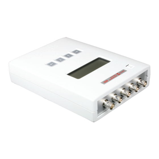
In power save mode the systems power supplies are shutdown inhibiting any signal output, power to the display is maintained. Auto power save mode will be reset by the next key press (display will blink and software issue text will be displayed). PARAMETER SETTINGS Parameter selection setting is achieved using the four keys left, right, up and down, the display is divided into two separate areas, on right hand side of the display is the 'mode' area, using the up... - Page 6 Figure 1: Install snap-on ferrite Figure 2: Plug in power PANEL DESCRIPTION AND ORENTATION Please follow the step by step instructions for set up and operation of the instrument. Refer to figure three for location on the output signal conditioners. The connectors provide the following outputs: TACHO: Provides a simulated tachometer signal with TTL (5 Volt) pulses ICP:...
- Page 7 The rear panel contains the power switch and charger input. The LED’s labeled F and C indicate fast charge (F) and trickle charge (C). The charge mode is selected automatically based on the charge level of the internal battery. DOCUMENT SUBJECT TO U.S. EXPORT CONTROLS, COMPLIANCE APPROVIAL REQUIRED PRIOR TO DISTRIBUTION IM4830, Page 7...
- Page 8 DOCUMENT SUBJECT TO U.S. EXPORT CONTROLS, COMPLIANCE APPROVIAL REQUIRED PRIOR TO DISTRIBUTION IM4830, Page 8...
- Page 9 DOCUMENT SUBJECT TO U.S. EXPORT CONTROLS, COMPLIANCE APPROVIAL REQUIRED PRIOR TO DISTRIBUTION IM4830, Page 9...
- Page 10 DOCUMENT SUBJECT TO U.S. EXPORT CONTROLS, COMPLIANCE APPROVIAL REQUIRED PRIOR TO DISTRIBUTION IM4830, Page 10...
-
Page 11: Calibration And Testing
BATTERY REPLACEMENT In the event the battery requires replacement, it can be replaced with an Endevco model EBT26. It can be installed by Endevco or the user can replace the battery. The battery is located in the upper right corner in figure 3. - Page 12 8.2.3 Depress the two left hand keyboard switches simultaneously to re-initialize the unit. Confirm the default settings: Frequency = 100 Hz, Sensitivity = 10.0 and g = 10.0. Frequency Accuracy 8.3.1 Connect the frequency counter to the “mV” output BNC connector. Set the 4830A sensitivity to 10.0 and the “g”...
- Page 13 444.0 313,96 310.8 – 317.1 555.0 392.44 388.5 – 396.4 666.0 470.93 466.2 – 475.6 777.0 549.42 543.9 – 554.9 888.0 627.91 621.6 – 634.2 999.0 706.40 699.3 – 713.5 DOCUMENT SUBJECT TO U.S. EXPORT CONTROLS, COMPLIANCE APPROVIAL REQUIRED PRIOR TO DISTRIBUTION IM4830, Page 13...
- Page 14 With the exception of the “Tach”, all other outputs of the 4830A are derived from the “mV” output. To verify their operation, suitable calibrated signal conditioners should be used, e.g. for the IEPE (Isotron) an Endevco 4416B, for an “S.E.”-and differential change, A Meggitt (Endevco) Model 6634C.
- Page 15 g Level mV Output Limits 10.00 70.7 mVrms 69.64 – 71.76 100.0 707.0 mVrms 696.4 – 717.6 1000.0 7070.0 mVrms 6964 - 7176 Amplitude Accuracy (S.E. Charge Output) 8.6.1 Connect the “S.E.” Charge Output to the input of the Model 6634B Signal Conditioner. Set the 6634B for: Type = SEPE, Sens = 10.00, FS = 20.0, Mode = g, DC = pK and Filter = Out.
-
Page 16: Troubble Shooting Guide
10.0 TECNICAL SUPPORT For technical assistance, contact the applications engineering department at Meggitt Sensing Systems or your local representative or international distributor. Questions If you have any questions regarding the use of this or any Endevco product, please contact Endevco Application Engineering at 1-800-982-6732 in North America, or your local sales representative.
Need help?
Do you have a question about the ENDEVCO 4830A and is the answer not in the manual?
Questions and answers