
Related Manuals for TURBRO GL9K115


Summary of Contents for TURBRO GL9K115
- Page 1 USER MANUAL SPLIT AIR CONDITIONER Model: GL9K115 GL9K230 GL12K115 GL12K230 GL18K230 Before using or installing your TURBRO Split Air Conditioner, please read this manual carefully and retain it for future reference.
- Page 2 1. Do not use means to accelerate the defrosting process or to clean, other than those recommended by the manufacturer. Should repair be necessary contact the TURBRO Customer Service Team. 2. Any repairs carried out by unqualified personnel may be dangerous.
-
Page 3: Table Of Contents
CONTENTS SAFETY INFORMATION ···········································································································01 PARTS DESCRIPTION ··············································································································03 OPERATING INSTRUCTIONS ··································································································06 ···························································································06 Operating from the Remote Control ·············································································································13 Operating from the App INSTALLATION INSTRUCTIONS ······························································································13 ··············································································································13 Indoor Unit Installation ···········································································································19 Outdoor Unit Installation ···············································································································26 Inspection before Use CLEANING ·································································································································27 ···································································································································27... -
Page 4: Safety Information
● Never attempt to operate this appliance if it visibly damaged, malfunctioning, disassembled or has missing or broken parts. This includes exposed wiring on a damaged cord or electrical plugin. All repairs and servicing must be performed by qualified service personnel. Use only authorized TURBRO factory OEM parts. - Page 5 ● During the installation or moving of the appliance, be careful not to pinch, crush, or damage the power cord. Always unplug the unit from the outlet before cleaning or maintenance operations. ● The batteries in the remote controller must be recycled or disposed of properly. For disposal of scrap batteries, please discard the batteries as sorted municipal waste at the accessible collection point.
-
Page 6: Parts Description
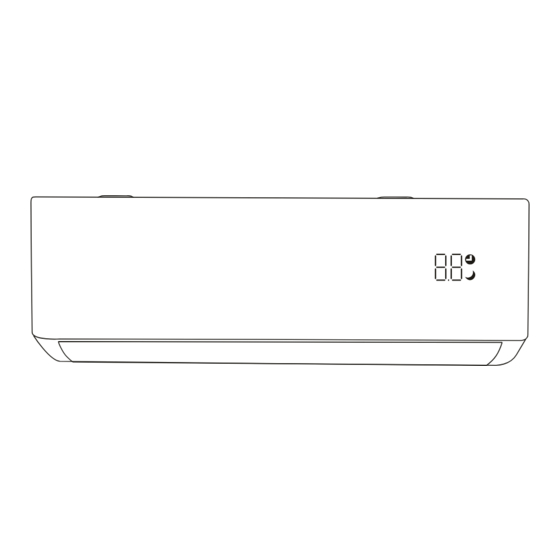
PARTS DESCRIPTION Indoor Unit Air Filter Air Inlet Front Panel Electric Control Box Manual Button Air Outlet Deflector NOTE: When the remote controller fails, press the Manual Button with insulation material. Current status Operation Respond Standby Press the manual button once It beeps briefly once and enters cool mode. - Page 7 Display Indicator for Timer, Temperature, and Error codes. Indicator for Timer Function. Indicator for Sleep Mode. Outdoor Unit Air Outlet Air Inlet Wiring Box Valve Box...
- Page 8 PARTS PARTS NAME QUANTITY Mounting plate Wall anchors 1 set Screws 1 set Screws for remote control holder 1 set Remote control AAA battery Remote control holder Drain joint Wall sleeve 1 set Refrigerant pipe (5m) Signal cable (with 4 colored wires)
-
Page 9: Operating Instructions
PARTS PARTS NAME QUANTITY Power cable Drain hose Sealing gum Insulation tape Rubber feet for outdoor unit Guide plate OPERATING INSTRUCTIONS Operating from the Remote Control... - Page 10 BUTTONS FUNCTION Turn the air conditioner on/off. Increase the set temperature; lengthen the time in TIMER setting. Decrease the setting temperature; reduce the time in TIMER setting. MODE Select the operation mode. Switch the TURBO mode on/off. TURBO Long press to switch the unit of temperature.
- Page 11 SYMBOLS MEANING SYMBOLS MEANING SIGNAL FAN SPEED AUTO MODE MUTE FUNCTION COOL MODE TURBO DRY MODE CHILD LOCK FAN MODE SLEEP MODE HEAT MODE I FEEL FUNCTION BATTERY ECO MODE TEMPERATURE FREEZE GUARD HEATING FUNCTION UP-DOWN AUTO SWING...
- Page 12 ▷ DRY MODE Ideal to reduce room humidity (spring and autumn, rainy periods or damp rooms, etc). ● Press the “MODE” button until the symbol appears on the remote screen. ● In this mode, the fan speed cannot be adjusted.
- Page 13 SLEEP Button This function is useful at night as it maintains the room at optimum temperature silently without excessive fluctuations in either temperature or humidity. ● Press the “SLEEP” button to set sleep mode. The icon will appear on the remote and indoor unit display.
- Page 14 ● Press the timer button again, the timer will be canceled and the will disappear. ECO Button In this mode the appliance automatically uses less compressor power to save energy without reducing the cooling effect. ● Press the “ECO” button to activate ECO mode and the appears on the display.
- Page 15 Self-Clean Function This function helps carry away the accumulated dirt, bacteria, etc from the indoor evaporator. To activate this function, turn off the indoor unit first, then press the “SWING ”and “SWING ” buttons simultaneously until hearing a beep. The “AC” will appear on the remote and the indoor unit display. This function will run for about 30 minutes, and it will return to the previous mode when complete.
-
Page 16: Operating From The App
Operating from the App This model is equipped with the Wi-Fi function. Using the AIRIA APP you can control the air conditioner via an iPhone or Android smartphone anywhere, even outside of your home. Please scan the QR code below or search “AIRIA”... - Page 17 Ceiling Floor Check the location meets the following requirements: ● Air inlet and outlet must be clear of obstructions, ensuring proper airflow throughout the room. ● Condensate can be easily and safely drained. ● All connections can be easily made to the outdoor unit.
- Page 18 Step 3: Drill Wall Hole ● Determine the location of the wall hole base on the position of the mounting plate. ● The hole should have a 70mm diameter at least and a small oblique angle to facilitate drainage to the outdoors.
- Page 19 ● There is a small amount of refrigerant in the pipe for testing before it leaves the factory. When unscrewing the screw cap of the refrigerant pipe, there will be a sound to indicate the refrigerant has not leaked during transportation.
- Page 20 ● Choose the correct cable size determined by the maximum operating current on the rating label and table below. Minimum Wire Model Min. Circuit Ampacity (A) Recommended Wire Gauge Cross-sectional Area (mm ) GL9K115 AWG 14+ GL9K230 AWG 18+ GL12K115 AWG 14+ GL12K230...
- Page 21 ● Connect the cables to the corresponding terminal according to the wiring diagram on the electric control box cover or the picture below. Make sure that they are well-connected. white green yellow (red) black Outdoor unit ● Screw the cable clamp to fasten the cables and reinstall the electric control box cover and front panel.
-
Page 22: Outdoor Unit Installation
Step 8: Mount Indoor Unit ● Slowly pass the wrapped bundle through the wall hole. ● Hook the top of the indoor unit on the mounting plate. Apply slight pressure to the left and right sides of the indoor unit, making sure the indoor unit is hooked firmly. - Page 23 Step 2: Install Drainage Hose ● Insert the drainage joint into the hole at the bottom of the outdoor unit. ● Connect the drainage hose to the joint and make the connection secure. Drainage hose Drainage joint Step 3: Fix Outdoor Unit ●...
- Page 24 ● According to the wiring diagram pasted inside the wiring cover or the picture below, connect the signal and power cables to the corresponding terminals. Ensure all connections are firm and secure. 9K115V, 12K115V yellow black black (black)
- Page 25 Step 5: Connect Refrigerant Pipe ● Unscrew the valve cover and press it down gently. ● Remove the protective caps from the end of the valves. Take off the plastic cover in the pipe ports. Take down the valve cover ●...
- Page 26 Note On Pipe Length The length of refrigerant pipe will affect the performance and energy efficiency of the unit. The refrigerant pipe included is 16.5ft (5 meters). If necessary, you can change the length of the refrigerant pipe by referring to the table below for specifications on the maximum length.
- Page 27 ▷ Flare pipe ends Fare nuts ● After removing burrs from the cut pipe, seal the ends with tape to prevent foreign materials from entering the pipe. ● Sheath the pipe with insulating material. Pipe ● Place flare nuts on both ends of the pipe. Make sure they are facing in the right direction, because you can’t put them on or...
- Page 28 ▷ Connect pipes When connecting refrigerant pipes, be careful not to use excessive torque or to deform the piping in any way. You should first connect the low-pressure pipe, then the high-pressure pipe. Step 6: Vacuum Pumping ● Use a spanner to take down the protective caps from the service port, low-pressure valve, and high-pressure valve.
-
Page 29: Inspection Before Use
Inspection Before Use Electrical safety inspection ● Check whether the power supply voltage complies with that on the rating label. ● Check whether there is any wrong or missing connection between the power cables, signal cables, and earth cables. -
Page 30: Cleaning
CLEANING Warning ● When cleaning, you must shut down the machine and cut off the power supply for more than 5 minutes. ● Under no circumstances should the air conditioner be flushed with water. ● Volatile liquid (e.g. thinner or gasoline) will damage the air conditioner, so only use a soft dry cloth or wet cloth dipped with neutral detergent to clean the air conditioner. -
Page 31: Maintenance Checklists
● Clean the filter with soapy water and air dry it. <40 (104 ● When installing the filter, first insert the lower end into the corresponding position of the unit, and then squeeze the upper end of the filter into the corresponding buckling position of the unit body. -
Page 32: Troubleshooting
D. Check and make sure the supply voltage is rated voltage range. stable and consistent with the rated range. E. Control Board/Fan motor E. Contact the TURBRO customer service team. Damaged. No air is blowing from Check and remove the obstacles blocking the Air outlet/Inlet is blocked. -
Page 33: Malfunction Codes
● Very strong smells coming from the appliance. MALFUNCTION CODES The unit has a self-diagnosis system to identify a number of malfunctions. Error messages will be displayed on the indoor unit display. If this is displayed, contact TURBRO service team. DISPLAY MALFUNCTION NAME... -
Page 34: Warranty & Customer Support
WARRANTY & CUSTOMER SUPPORT WARRANTY TURBRO provides a 1-year limited warranty for TURBRO products from the date of purchase, subject to the following conditions and limitations outlined below. What is covered? ● This warranty is limited to the repair or replacement of part(s) proved to be defective in material or workmanship, after said defect is confirmed by the manufacturer's inspection. - Page 35 323 438-3334...
Need help?
Do you have a question about the GL9K115 and is the answer not in the manual?
Questions and answers