
Subscribe to Our Youtube Channel
Related Manuals for Marco 1000944 Series


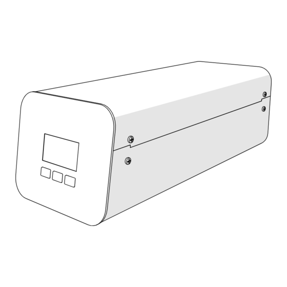
Summary of Contents for Marco 1000944 Series
- Page 1 POUR’D Control Box Service Manual 1000944# 1000944EU 1001944US Ireland Tel: +353 (1) 295 2674 www.marcobeveragesystems.com UK Tel: +44 (0207) 2744577 Page 1 of 17...
-
Page 2: Table Of Contents
CONTENTS: 1. Introduction …………………………………………………………………………………………………………………… 2. Safety Instructions …………………………………………………………………………………………………………. 3. Specifications …………………………………………………………………………………………………………………. 4. Installation …………………………………………………………………………………………………………………….. 4.1 Control Box Installation ……………….……………………………………………………………………….. 5. Menu Navigation …………………………………………………………………………………………………………… 5.1 User Settings …………………………………………………………………………………………………………. 5.2 Advanced Settings …..…………………………………………………………………………………………….. 6. Routine Maintenance/Internal Access …………………………………………………………………………… 6.1 Top Lid Removal ……………………………………………………………………………………………………… PCB Replacement …..…………………………………………………………………………………………….. -
Page 3: Introduction
1. INTRODUCTION The information provided in this manual is intended to assist in the installation and maintenance of the Marco POUR’D Control Box. Please read the instructions carefully to prevent accidents and ensure an efficient installation. This manual is not a substitute for any safety instructions or technical data affixed to the machine or its packaging. -
Page 4: Specifications
3. SPECIFICATIONS Control Box: POUR’D 1000944#, 1000944EU, 1001944US Ratio 12:1 up to 30:1 Performance Minimum Delivery 120ml Earthed Mains Plug to IEC 230vac (UK – 3-Pin Plug, BS1363) Mains Connection (EU – CEE7 Schuko) Electrical (US (120v – NEMA 5-15) @230V Rating @120v... -
Page 5: Installation
4. INSTALLATION 4.1 Control Box Installation Electrical Installation: • Electrical specification: 70W-230VAC-50/60Hz 70W-120VAC-50/60Hz • A moulded IEC C19 CEE7 EU / NEMA 5-15, 15A/125V power cord is provided. This should be plugged into the IEC connection on the rear of the control box and plugged into a suitable power outlet. -
Page 6: Control Box Installation
4.1 POUR’D Control Box Installation (cont.) Page 6 of 17... -
Page 7: Menu Navigation
5. MENU NAVIGATION There are 3 menu ‘levels’ to the POUR’D settings. Level 1 – User Settings Level 2 – Advanced Settings Enter by pressing all 3 Enter by pressing all 3 buttons simultaneously buttons simultaneously. for > 3 <6 seconds. 5.1 LEVEL 1: User Settings The screens displayed to the User depend on which machine type the software has been set to. -
Page 8: Advanced Settings
5.2 LEVEL 2: Advanced Settings (Hold all 3 buttons simultaneously for >3 <6 seconds) For calibration you will need a container and a scale 5.2.1 Calibration Concentrate Pump 1.Press Go! To enter Concentrate Pump calibration 2.It’s a two-stage calibration. 3.Press Go! To start dispensing 4.Use “+”... - Page 9 Calibration Hot Water (IF THERE IS A BOILER) 1.Two stage calibration 2.Press Go! To start dispensing 3.Use “+” or “-“ to write the Click Go! When ready. result and press next The difference between both dispense, is time. POUR’D will adjust itself to have the correct amount delivered.
-
Page 10: Routine Maintenance/Internal Access
Chiller needs to be activated to be able to dispense cold and sparkling water 6. ROUTINE MAINTAINENCE/INTERNAL ACCESS Maintenance should be carried out by Marco approved technicians only. 6.1 Top Lid Removal: 1. Remove the Top Sides screws from the sides. -
Page 11: Pcb Replacement
6.2 PCB Replacement: 1. Remove the 2 Low Front screws. 2. Pull the front fascia panel and disconnect the wiring. 3. Remove 4 screws to release PCB from Front Fascia panel. 6.3 Power Supply Removal: 1. Remove two side screws 2. -
Page 12: Pump Removal
6.4 Pump Removal: 1. Remove the screws holding the Back Panel. 2. Careful disconnect all houses going to the pump and flowmeter. 3. Pull the Back Panel out 4. Remove 4 nuts that holds the pump in place 5. Pull the pump up 6. -
Page 13: Flowmeter Removal
6.5 Flowmeter Removal: 1. Turn the machine upside down and remove the three screws. 2. Flow meter will be loose and ready to remove 3. Remove both elbow connectors. Page 13 of 17... -
Page 14: Solenoid Valve Replacement
6.6 Solenoid Valve Replacement 1. Remove screws holding the solenoid to the Rear Panel. 2. Solenoid is free to be replaced. Page 14 of 17... -
Page 15: Diagnostics/Trouble Shooting
7. DIAGNOSTICS TROUBLESHOOTING Page 15 of 17... -
Page 16: Electrical Schematics
8. ELECTRICAL SCHEMATICS Wiring Diagram Page 16 of 17... -
Page 17: Spare Parts
9. SPARE PARTS Page 17 of 17...
Need help?
Do you have a question about the 1000944 Series and is the answer not in the manual?
Questions and answers