Table of Contents
Advertisement
Quick Links
Advertisement
Table of Contents

Related Manuals for CNC4PC THC-1


Summary of Contents for CNC4PC THC-1
- Page 1 USER’S MANUAL VER. 2 THC-1 – TORCH HEIGHT CONTROL Rev.2 APRIL 2023...
-
Page 2: Table Of Contents
USER'S MANUAL TABLE OF CONTENTS Contents Page # OVERVIEW ..........................1 FEATURES ..........................1 DESCRIPTION ........................2 TERMINAL BOARD ......................3 POWER ............................ 3 DIVIDED INPUT ........................3 TORCH VOLTAGE ........................4 OUTPUT SIGNALS ........................4 CONFIGURE MENU ......................5 DESCRIPTION SCREEN ....................6 SET POINT (SP) ........................6 VOLTAGE ARC (ARC)...................... -
Page 3: Overview
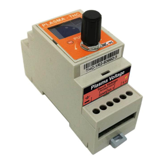
OVERVIEW This module allows controlling the height the plasma torch head relative to work piece during plasma CNC operation, it supports either raw torch head voltage or an input of 0-10VDC, the ARC OK, UP and DOWN outputs are isolated. FEATURES •... -
Page 4: Description
DESCRIPTION User’s Manual Page 2... -
Page 5: Terminal Board
TERMINAL BOARD POWER Requires a 10 to 30VDC at 100mA Power Supply, “This board is electrically isolated through a DC-DC converter.” WARNING: Check the polarity and voltage of the external power source and connect the 10VDC to 30VDC and GND. Overvoltage or reverse-polarity power applied to these terminals can cause damage to the board, and/or the power source. -
Page 6: Torch Voltage
TORCH VOLTAGE NOTE: It is preferable to use the divided voltage instead of the torch voltage. The Torch voltage can be very high and there could be many safety implications in wiring this to the controller. The high voltage could also be a possible source of noise. -
Page 7: Configure Menu
CONFIGURE MENU • Push the knob to enter configuration mode. • Navigate through the configuration menu by pressing the knob. • Turn the knob to adjust the value. • Push the knob to set the value and navigate to the next parameter or until you reach the run mode. -
Page 8: Description Screen
DESCRIPTION SCREEN SET POINT (SP) SP is the target voltage to be achieved. NOTE: If auto_SetPoint is activated the knob it's disabled VOLTAGE ARC (ARC) Limit from 40 to 400VDC, True Voltage measured at the terminals or the voltage divider. HYSTERESIS (HYS) Is the tolerance or (+/-) voltage range used to generate an adjustment. -
Page 9: Test Mode (Test)
TEST MODE (TEST) • Press the knob three times to enter test mode. • Turn the knob up or down to make the spindle move. • To exit test mode, press the knob once. DIVIDED VOLTAGE CONFIGURATION • Press the knob three times to enter the setting mode •... -
Page 10: Auto_Setpoint
AUTO_SETPOINT Automatically establishes the SetPoint based on the cutting height that is set. ACTVATE DISABLE If auto_SetPoint is activated the knob it's disabled and the word Auto is displayed on the screen User’s Manual Page 8... -
Page 11: Wiring Sample
WIRING SAMPLE Disclaimer: Use caution. CNC machines can be dangerous machines. Neither DUNCAN USA, LLC nor Arturo Duncan is liable for any accidents resulting from the improper use of these devices. This product is not a fail-safe device and it should not be used in life support systems or in other devices where its failure or possible erratic operation could cause property damage, bodily injury or loss of life.
Need help?
Do you have a question about the THC-1 and is the answer not in the manual?
Questions and answers