
Related Manuals for Robur Supercromo D-LBR167


Summary of Contents for Robur Supercromo D-LBR167
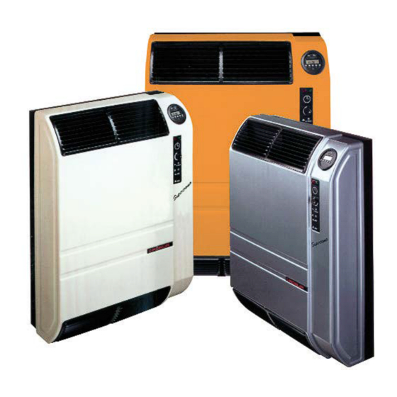
- Page 1 Installation, use and maintenance manual D-LBR167 - Supercromo Independent gas-fired convectors with direct exchange to heat small and medium sized rooms Fired by natural gas/LPG...
- Page 2 The rights of those who have legitimately filed the registered trademarks contained within this publication are not affected. With the aim of continuously improving the quality of its products, Robur S.p.A. reserves the right to modify the data and contents of this Installation, use and maintenance manual without prior notice.
-
Page 3: Table Of Contents
TABLE OF CONTENTS Introduction Supplied material ..........p. 10 ................p. 4 Fuel gas supply ............ p. 10 Recipients ..............p. 4 Combustion products exhaust ...... p. 11 Available languages ..........p. 4 Installation procedure ........p. 13 II Symbols and definitions ......... p. 4 4 Electrical installer ............ -
Page 4: Iintroduction
Appliance/Unit = equivalent terms, both used to refer to WARNING the independent direct exchange gas-fired convector. TAC = Technical Assistance Centre authorised by Robur. First start-up = appliance commissioning operation NOTE which may only and exclusively be carried out by a TAC. -
Page 5: Iii.2 Compliance
Warnings Distance from combustible or flammable mate- „ Before performing any operation on gas ducting components, close the gas valve. rials „ Upon completing any procedure, perform the „ Do not deposit flammable materials (paper, dilu- tightness test according to regulations in force. ents, paints, etc.) near the appliance. -
Page 6: Iii.3 Exclusions Of Liability And Warranty
Warnings III.3 EXCLUSIONS OF LIABILITY AND 2016/426/EU "Gas Appliances Regulation" as amend- ▶ WARRANTY ed and added. 2014/30/EC "Electromagnetic Compatibility Directive" ▶ as amended and added. Any contractual or extra-contractual liability of the 2014/35/EC "Low Voltage Directive" as amended and ▶... -
Page 7: Features And Technical Data
Features and technical data FEATURES AND TECHNICAL DATA FEATURES to choose the desired temperature (set on the regulation thermostat) and, for the 3002 model, the operating period 1.1.1 Operation (set on the programmable timer). The sealed combustion chamber is the best guarantee of The Supercromo gas-fired convector is an independent safety for the environment in which the gas-fired convec- heating appliance with sealed combustion chamber and... -
Page 8: Dimensions
Features and technical data DIMENSIONS Figure 1.1 Dimensions CONTROLS panel supplied as standard, which includes a thermostat for adjusting the temperature and a programmable timer 1.3.1 Control device (standard on 3002 model, optional on 3001 model). For further information please refer to Paragraph The operation of the appliance is regulated by the control 6.2 ... -
Page 9: Transport And Positioning
Transport and positioning TRANSPORT AND POSITIONING WARNINGS appliance is installed on surfaces or walls that are not suitable to support its weight. Damage from transport or installation The appliance's flue gas exhaust must not be im- The manufacturer shall not be liable for any dam- mediately close to openings or air intakes of build- age during appliance transport and installation. -
Page 10: Heating Engineer
Heating engineer HEATING ENGINEER SUPPLIED MATERIAL Installation jig in cardboard. ▶ WARNINGS Wall support bracket. ▶ Air duct Ø 49 mm, length 500 mm. ▶ 3.1.1 General warnings Flue gas duct Ø 35 mm, length 500 mm. ▶ External flue gas terminal in aluminium alloy. ▶... -
Page 11: Combustion Products Exhaust
Heating engineer 3.3.3 Gas pipes sizing tuations in the inlet pressure. In order to limit the extent of these variations, it is necessary to appro- The gas pipes must not cause excessive pressure drops priately define the diameter of the gas inlet pipe and, consequently, insufficient gas pressure for the to be adopted based on the length and pressure appliance. - Page 12 Heating engineer Warnings gas with lock-out of the appliance). „ It is forbidden to install coaxial pipes with a vertical „ The installation of pipes with a vertical downward outlet upwards (due to rain, water, objects infiltra- outlet is prohibited (leads to recirculation of flue tion, with consequent lock-out of the appliance).
-
Page 13: Installation Procedure
D-GPP001, available on the Robur website. At the design stage, it must be verified that the sum of the pressure drop of all components used does not exceed the value of the available residual head (Table 3.2 ... - Page 14 Heating engineer The Ø 50 mm hole for the duct can be made with a 20 cm in length (flue gas pipe 200 + 33 mm, air in- suitable core drill or by means of a succession of small- take pipe 200 + 2 mm). er holes made with a simple drill on the perimeter to be removed.
-
Page 15: Electrical Installer
Electrical installer Figure 3.7 Casing fixing screws Figure 3.9 Support bracket detail Supports Fastening screws 3.5.2 Install the windproof terminal Figure 3.8 Positioning the flue gas exhaust pipe 1. When the appliance is installed, place the aluminium windproof terminal to the outdoor wall so that it en- gages with the end of the flue gas pipe and mark the position of the three holes for the expansion plugs (see Figure 3.10 ... -
Page 16: Electrical Power Supply
5.1.2 Abnormal or hazardous installation out by a Robur TAC. NEITHER the user NOR the in- situations stallation technician is authorised to perform such Should any abnormal or hazardous installation situations operations, under penalty of voiding the warranty. - Page 17 First start-up The gas supply circuit is equipped with a gas so- Figure 5.1 Valve assembly lenoid valve with double safety shutter and pres- sure regulator to control the gas flow. All models are factory-set to operate with natural gas and can be converted to LPG (see Paragraph 5.3 ...
-
Page 18: Gas Changeover
First start-up 3. Unscrew the B plug with a no. 19 wrench. After the adjustment, stop and start the appliance 4. Using a no.10 socket wrench introduced in the open- and check that burner pressure has stabilised. If necessary perform the adjustment again. ing, unscrew the nozzle holder A. -
Page 19: Normal Operation
This section is for the end user. Figure 6.1 Control panel The use of the device by the end user is only per- mitted after the Robur authorised TAC has com- AUTO pleted the first start-up. The operation of the Supercromo gas-fired heaters is con- RESET trolled by the supplied control panel. -
Page 20: Programmable Timer
Normal operation reset button A. Figure 6.2 TM619-2 timer 8. Once the appliance is switched on, turn knob B on the thermostat clockwise to increase the room tempera- ture and counterclockwise to decrease it. 9. The fan starts automatically only when it receives the consent of the ventilation control thermostat, i.e. - Page 21 Normal operation 6.4.3.2 Set the on/off programs 7. Use cable 93 (black) of the cable kit to connect the pro- 1. Press the TIMER button. The LCD screen will show grammable timer terminals 2 and 4 to each other. 8. Remove the room thermostat, disconnect cable 7 (switch-on program 1 ON).
-
Page 22: Maintenance
Maintenance The programmed operation is resumed returning to the Figure 6.4 15 combination of days in a week AUTO mode, starting from the following time program. 1. MO TU WE TH Program skip functions are effective only when the 2. MO programmable timer is running in AUTO mode. -
Page 23: Safety Devices
Maintenance SAFETY DEVICES „ There is a full electricity supply. „ The gas is supplied. „ The supply pressure at the burner is within the Electricity outage specified tolerance range. Only this point proceed with specific The gas-fired convector is switched off by closing troubleshooting. -
Page 24: Appendices
�me limita�on with black bulb sensor Permanent pilot flame power requirement Pilot flame power requirement (if N.A. pilot applicable) Contact details Robur SPA, Via Parigi 4/6, I-24040 Zingonia (BG) (*) NO = nitrogen oxides... - Page 25 �me limita�on with black bulb sensor Permanent pilot flame power requirement Pilot flame power requirement (if N.A. pilot applicable) Contact details Robur SPA, Via Parigi 4/6, I-24040 Zingonia (BG) (*) NO = nitrogen oxides Installation, use and maintenance manual – Supercromo...
- Page 28 Robur mission Robur is dedicated to dynamic progression in research, development and promotion of safe, environmentally-friendly, energy-efficiency products, through the commitment and caring of its employees and partners. Robur S.p.A. advanced technologies for air conditioning via Parigi 4/6 24040 Verdellino/Zingonia (BG) Italy +39 035 888111 - F +39 035 884165 www.robur.it robur@robur.it...
Need help?
Do you have a question about the Supercromo D-LBR167 and is the answer not in the manual?
Questions and answers