
Related Manuals for WTC MedWeld 5000

Summary of Contents for WTC MedWeld 5000
- Page 1 MedWeld 5000 Integrated Weld Control Operator’s Guide for Software #F04200 Revision Modified: 6/6/07 Part No. M-032175 Copyright © 2007, WTC...
- Page 2 MedWeld 5000 Operator’s Guide for #F04200 M-0273 June, 2007...
-
Page 3: Table Of Contents
If You Need Help ...............vii Welding Technology Corp. (WTC) ..........vii By Phone or Fax: ................vii By E-mail: ..................vii On the Web: ..................vii Symbols Used in This Manual ..........viii Revision History ..............ix Safety Dangers ...............ix How to Use this Manual ............xi... - Page 4 Output Abbreviations ...............15 Chapter 4 Weld Schedules ..........1 What is a Weld Schedule? ............1 Software Capabilities ..............2 List of Functions ..............3 MedWeld 5000 Functions ..............3 Function Descriptions .............4 Delay Functions .................4 Weld Functions ..................5 MedWeld 5000 Technical Reference Manual Modified: 6/6/07...
- Page 5 What is a Stepper? ..............1 Linear Steppers ..................2 Auxiliary Weld Counters ..............2 Default Linear Stepper Profile ............3 Display at the DEP-100S ............4 Chapter 8 Fault Conditions ..........1 Chapter 9 Hardware Troubleshooting .......1 Power Supply .................1 Processor .................2 MedWeld 5000 Technical Reference Manual Modified: 6/6/07...
- Page 6 Weld Processor ...............3 Solving Typical Problems ............5 MedWeld 5000 Technical Reference Manual Modified: 6/6/07...
-
Page 7: If You Need Help
Getting Started If You Need Help . . . Welding Technology WTC is committed to quality products, service and support. Our service Corp. (WTC) department maintains an assistance hotline to assist with application or troubleshooting during normal business hours. By Phone or Fax:... -
Page 8: Symbols Used In This Manual
Caution: This symbol denotes when insufficient or lacking compliance with the instructions may damage equipment or files. NOTE: This convention informs the user about special features, or where to find more information. viii Modified: 6/6/07 MedWeld 5000 Operator’s Guide M-032175... -
Page 9: Revision History
BURNS, INTERNAL INJURIES and/or DEATH. Refer all necessary service on this machine ONLY to qualified maintenance personnel. Caution: When lifting any weight over 20 kg (~45 lb.), use either a two-man lift or an assisted lift. MedWeld 5000 Operator’s Guide Modified: 6/6/07 M-032175... - Page 10 Inspect the enclosure for any potential shipping WARNING! damage, loose connections, or packing materials inside the cabinet before operation! WTC does NOT recommend drilling any holes in WARNING! the cabinet! If additional holes are required, make certain all components are covered to adequately protect from metal debris.
-
Page 11: How To Use This Manual
This manual is designed as a reference guide. Use it as you would a dictionary. See the Table of Contents to locate the instructions or information you require. For additional details, you are referred to the appropriate sections and page numbers. MedWeld 5000 Operator’s Guide Modified: 6/6/07 M-032175... -
Page 12: Software Updates
Software Updates WTC reserves the right to make substitutions or changes as required to the hardware or software described in this manual. This manual may be periodically updated to reflect software changes that will affect operation of the equipment described. -
Page 13: Working With Static-Sensitive Devices
The measured static voltage at a workstation MUST NOT exceed 50 volts. Contact For detailed information about ESD precautions, contact Information ESD Association e-mail: eosesd@aol.com Web: www.esda.org Voice: 315–339–6937 e-mail: info@esda.org Fax: 315–339–6793 MedWeld 5000 Operator’s Guide Modified: 6/6/07 xiii M-032175... -
Page 14: Copyright
Copyright WTC software and publications are copyrighted and all rights are reserved by WTC. Distribution and sale of software is intended for the use of the original purchaser, and only for use on a single machine. Copying, duplicating, selling or otherwise distributing this software is a violation of law. - Page 15 Getting Started This page is intentionally left blank. MedWeld 5000 Operator’s Guide Modified: 6/6/07 M-032175...
-
Page 16: Problem Report Form
Fault code display. When a fault or error occurs, the Product ### displays a status code. Indicate each code that is displayed: Description of the problem: Sequence of events leading to the problem: Drawing number(s) of schematic(s) shipped with the Product ###: Modified: 6/6/07 MedWeld 5000 Operator’s Guide M-032175... - Page 17 Getting Started This page is intentionally left blank. MedWeld 5000 Operator’s Guide Modified: 6/6/07 xvii M-032175...
-
Page 18: Your Feedback Welcome Here
Fax it at (248) 477-8897. Comments for Your Name: Date: Time: Feedback Form Company Name: Phone: Company Address: City: State: ZIP: Program/Revision #: # of Manuals at your site: Document Number/Name: Your comments: xviii Modified: 6/6/07 MedWeld 5000 Operator’s Guide M-032175... - Page 19 Getting Started This page is intentionally left blank. MedWeld 5000 Operator’s Guide Modified: 6/6/07 M-032175...
- Page 20 Getting Started Modified: 6/6/07 MedWeld 5000 Operator’s Guide M-032175...
-
Page 21: Medweld 5000 Overview
These advanced integration options provide added flexibility to the WTC design, which provides full-function programming capabilities. The MedWeld 5000 can support voltages as low as 240VAC and up to 600VAC with the proper configuration. The control compensates for changes in the welding environment by monitoring the voltage and increasing the current as required to ensure consistent welds. -
Page 22: Welding With An Ac Control
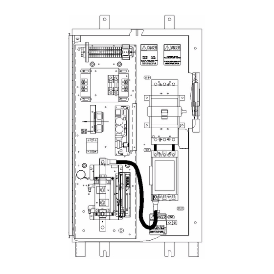
• SPC data (Group, bin and part number) This data can be reviewed this data with a programming device (such as the WTC DEP-100S Hand-Held Terminal), or use it for data analysis by programs such as WTC’s WebVIEW. • Sequence number executed •... - Page 23 MedWeld 5000 Overview This image shows a standard MedWeld 5000 AC weld control configuration. MedWeld 5000 Operator’s Guide for #F04200 1 - 3 M-032175 June 2007...
-
Page 24: Timer Unit
I/O, data and serving web pages from the timer module. This communications module has an ethernet RJ-45 connector located on the bottom side of the timer. 1 - 4 MedWeld 5000 Operator’s Guide for #F04200 M-032175 June 2007... -
Page 25: Devicenet Integration
Client, Server or both. The network can have up to 64 node addresses, and each node supports an infinite number of I/O. NOTE: For more information on DeviceNet, contact your WTC representative. MedWeld 5000 Operator’s Guide for #F04200 1 - 5... -
Page 26: Component Descriptions
This contactor removes power from the weld transformer using the ISOLATION CONTACTOR output at the CIOM module or using relay control. MedWeld 5000 controls can be ordered with or without isolation contactors. These devices must be sized properly for the weld application and use proper wiring sizes from the SCR assembly to the weld transformer. -
Page 27: Scr Assembly
(depending on the firing mode) and the power factor and Check for shorted or misfiring SCR(s). All of these signals are transmitted over firing card connector J2 and weld processor card connector J3. MedWeld 5000 Operator’s Guide for #F04200 1 - 7 M-032175 June 2007... -
Page 28: Timer Unit
All safety related major faults are FAULT only, and can not be set to an alert. Optional Components The MedWeld 5000 series of weld control also offers some optional components for installation. •... - Page 29 8 discrete outputs that can be used for any type of external hardwired I/O. This board is powered by 24VDC and can be powered by the internal control power. MedWeld 5000 Operator’s Guide for #F04200 1 - 9 M-032175 June 2007...
- Page 30 MedWeld 5000 Overview 1 - 10 MedWeld 5000 Operator’s Guide for #F04200 M-032175 June 2007...
-
Page 31: Chapter 2 Installing The Medweld 5000
Installing the MedWeld 5000 To install the MedWeld 5000, you must provide the required DeviceNet communications, configure the unit for the MedLAN network, set the network address and program the timer unit to meet your application requirements. These steps are described in the sections that follow. -
Page 32: Devicenet Integration
DeviceNet system must be terminated with 121 Ohms, 1%, 1/4W terminating resistors. NOTE: The MedWeld 5000 is designed to use either DeviceNet or Discrete I/O. When configuring the I/O for your application, be certain that the DeviceNet and Discrete I/O do not conflict with each other. Conflicting 2 - 2 MedWeld 5000 Operator’s Guide for #F04200... -
Page 33: Providing Medlan Connections
BEFORE communication over the MedLAN channel is possible. Networking takes place over the MedLAN channel. Use a WTC data entry device DEP-100, or WebView for network communications or to program a single weld control. -
Page 34: Cable Routing Requirements
If the MedLAN cable must cross this wiring, it must do so at a 90° angle. Setting the timer The MedWeld 5000 uses MedLAN (WTC’s proprietary Local Area Network) to create a communications network between devices. After MedLAN Address... - Page 35 DeviceNet node address will be changed to match the port address and vise versa. Use the WTC DEP-100S to program the MedLAN address for each individual weld control, through the top (DEP) port of the timer unit.
-
Page 36: Programming The Timer Unit
I/O was to use DeviceNet communications, a user would program the flexible I/O for the Fieldbus to their I/O map. Then the user would program flexible I/O map for I/O Mapping (discrete) to NONE. 2 - 6 MedWeld 5000 Operator’s Guide for #F04200 M-032175 June, 2007... -
Page 37: Flexible I/O List
PROGRAM DISPLAY SECURITY HEAT DISPLAY SECURITY USER INPUT 1 USER INPUT 2 USER INPUT 3 USER INPUT 4 USER INPUT 5 USER INPUT 6 RETRACT 1 RETRACT 2 MedWeld 5000 Operator’s Guide for #F04200 2 - 7 M-032175 June, 2007... - Page 38 PRESSURE SELECT 3 PRESSURE SELECT 4 USER OUTPUT 1 USER OUTPUT 2 USER OUTPUT 3 USER OUTPUT 4 USER OUTPUT 5 USER OUTPUT 6 RETRACT VALVE 1 RETRACT VALVE 2 2 - 8 MedWeld 5000 Operator’s Guide for #F04200 M-032175 June, 2007...
-
Page 39: Dep-100S Programming Device
WTC’s Network Software (Bank & Weld Gateway) or • Robot manufacturer teach pendant. DEP-100S WTC’s DEP-100S Programming Device is a data entry device. Use it to program one, several or up to 30 timer units on a MedLAN network. Programming Device •... -
Page 40: Ethernet/Ip Dep
Installing the MedWeld 5000 Ethernet/IP DEP The WTC Ethernet/IP DEP (Data Entry Panel) is a pendant that can scan for timers over a single ethernet line and allows users to connect to any of the timers in the same subnet mask as the Ethernet DEP. -
Page 41: Wtc Network Software
Robot Manufacturer WTC works closely with all the major robot manufacturers to allow the use of controlling the weld control from these points. Please see the Pendant robot manufacturer documentation for futher information on the capabilities of the specific programming device. - Page 42 Installing the MedWeld 5000 2 - 12 MedWeld 5000 Operator’s Guide for #F04200 M-032175 June, 2007...
-
Page 43: Communications And I/O
The following sections describe each option and the I/O provided. CIOM and Local I/O When the MedWeld 5000 is part of a network (as with the DeviceNet integration), the DeviceNet or Ethernet/IP provides global I/O and the CIOM module will monitor discrete control of certain critical inputs and outputs. -
Page 44: Local Outputs
This device is used as an interrupt to protect against voltage traveling to the primary of the weld transformer. The iso contactor will drop out only when a major fault is generated, or during an control stop condition. 3 - 2 MedWeld 5000 Operator’s Guide for #F04200 M-032175 June, 2007... -
Page 45: Organization Of The Devicenet I/O
Weld Mode. If this input is open, the control is in No Weld Mode. With this input open (No Weld Mode), the control will turn on the NO WELD Output and no weld current will flow. MedWeld 5000 Operator’s Guide for #F04200 3 - 3 M-032175 June, 2007... - Page 46 This input will reset all the steppers in Group 1 or 2 to Step 1 and the total weld count to 0. TIP DRESS Input This input moves the stepper to the beginning of the second step in the stepper profile. 3 - 4 MedWeld 5000 Operator’s Guide for #F04200 M-032175 June, 2007...
- Page 47 HIGH. This bit can be driven via DeviceNet or Ethernet/IP, but is typcially a hardwired switch at the control itself. MedWeld 5000 Operator’s Guide for #F04200 3 - 5 M-032175 June, 2007...
- Page 48 Caution: On power-up, it may be necessary to activate the RETRACT Input (1 or 2) to energize the output, to correct the internal state of the retract pilot. 3 - 6 MedWeld 5000 Operator’s Guide for #F04200 M-032175 June, 2007...
-
Page 49: User Inputs 1 - 8
This input must be used in conjunction with the PRM MODE SECURITY Input. If this input is active (locked HIGH), there can be NO changes made to any of the programmable data except under the Stepper Status Mode. MedWeld 5000 Operator’s Guide for #F04200 3 - 7 M-032175 June, 2007... -
Page 50: Outputs
This output is normally OFF, indicating that the control is functioning normally. If the control shuts down as the result of a fault condition, this output will be turned ON. NO FAULT Output 3 - 8 MedWeld 5000 Operator’s Guide for #F04200 M-032175 June, 2007... -
Page 51: Weld Complete Output
The control is in Weld Mode, • NO faults exist, • The CONTROL STOP input is HIGH, • The WCU is synchronized with the line voltage, • System cooling is provided: MedWeld 5000 Operator’s Guide for #F04200 3 - 9 M-032175 June, 2007... - Page 52 1– 8. Do NOT confuse this label (Output #1, for example) used by the weld function with an actual output position. That is, User Output #1 is NOT NECESSARILY assigned to output #1. 3 - 10 MedWeld 5000 Operator’s Guide for #F04200 M-032175 June, 2007...
-
Page 53: Devicenet Bitmap
Spare Input Spare Spare Input Spare Spare Input Spare Spare Input Spare Spare Input Spare Spare Input Spare Spare Input Spare Spare Input Spare Spare Input Spare Spare MedWeld 5000 Operator’s Guide for #F04200 3 - 11 M-032175 June, 2007... - Page 54 Spare Output Spare Spare Output Spare Spare Output Spare Spare Output Spare Spare Output Spare Spare Output Spare Spare Output Spare Spare Output Spare Spare Output Spare Spare 3 - 12 MedWeld 5000 Operator’s Guide for #F04200 M-032175 June, 2007...
-
Page 55: Ethernet/Ip Bitmap
The last weld in the last step of the stepper was reached. I:1.[6] Output Ready to Weld The control is ready to begin welding. I:1.[7] Output Tip Dressed Tip Dress MedWeld 5000 Operator’s Guide for #F04200 3 - 13 M-032175 June, 2007... -
Page 56: Dep-100S & Ethernet/Ip Dep Abbreviations
ISOLATION CONTACTOR (AUXILIARY CONTACTS) Input User Input #1 User Input #2 User Input #3 User Input #4 User Input #5 User Input #6 User Input #7 User Input #8 3 - 14 MedWeld 5000 Operator’s Guide for #F04200 M-032175 June, 2007... -
Page 57: Output Abbreviations
INITIATE ACKNOWLEDGE Output IACK User Output #1 User Output #2 User Output #3 User Output #4 User Output #5 User Output #6 User Output #7 User Output #8 MedWeld 5000 Operator’s Guide for #F04200 3 - 15 M-032175 June, 2007... - Page 58 Communications and I/O 3 - 16 MedWeld 5000 Operator’s Guide for #F04200 M-032175 June, 2007...
-
Page 59: Weld Schedules
Weld Schedules The MedWeld 5000 control is capable of storing up to 63 unique weld schedules. Each weld schedule can then be assigned to one of 63 independent steppers. This chapter does not describe how to create or modify a weld schedule. -
Page 60: Software Capabilities
Weld Schedules Software Capabilities The MedWeld 5000 provides commands for: • Assigning a stepper to a schedule, • Defining a linear stepper program, • Turning selected outputs on or off, wait statements and • Providing weld current in desired format. -
Page 61: List Of Functions
WAIT FOR INPUT #n TO BE (0=OFF, 1=ON) WAIT nnn CYC FOR PRESSURE SWITCH INPUT WAIT FOR PRESSURE SWITCH INPUT WAIT FOR WELD PROCEED SET VALVE #n CYLINDER PRESSURE TO nnnn PSI MedWeld 5000 Operator’s Guide for #F04200 4 - 3 M-032175 June, 2007... -
Page 62: Function Descriptions
During these functions, weld current does not flow and I/O status is not changed. Open the list of delay functions on the DEP by pressing F1. SQUEEZE nn CYCLES COOL nn CYCLES HOLD nn CYCLES 4 - 4 MedWeld 5000 Operator’s Guide for #F04200 M-032175 June, 2007... -
Page 63: Weld Functions
30-37) have Automatic Current Compensation. Functions using the ACC firing mode specify a set amount of secondary current, displayed as nnnnn AMPS. ACC monitors the current during each MedWeld 5000 Operator’s Guide for #F04200 4 - 5 M-032175 June, 2007... - Page 64 IMPULSE= nn HEAT CY, nn COOL CY (nn=1-99) When Function appears before any weld function in a schedule, the control displays IMP (impulses) rather than CY (cycles) to indicate the weld control will pulsation weld. 4 - 6 MedWeld 5000 Operator’s Guide for #F04200 M-032175 June, 2007...
-
Page 65: Weld Functions Using Automatic Current Compensation
When the function appears before any weld function in a schedule, the control displays IMP (impulses) rather than CY (cycles) to indicate the weld control will pulsation weld. MedWeld 5000 Operator’s Guide for #F04200 4 - 7 M-032175 June, 2007... -
Page 66: Weld Functions That Adjust Current
When this function appears before any weld function, the control displays IMP (impulse) rather than CY (cycles) to indicate the weld control will pulsation weld. 4 - 8 MedWeld 5000 Operator’s Guide for #F04200 M-032175 June, 2007... - Page 67 This function only affects the next function in a weld schedule. It should appear before every weld or slope function you want to pulsation weld in the schedule. MedWeld 5000 Operator’s Guide for #F04200 4 - 9 M-032175 June, 2007...
-
Page 68: Special Functions
This function allows the operator to call a valve OFF statement after any valve ON statement has been called. TURN ON OUTPUT #n The control turns this output ON when called in a weld schedule. 4 - 10 MedWeld 5000 Operator’s Guide for #F04200 M-032175 June, 2007... - Page 69 This continues until the processor detects that the WELD INITIATE input has been removed. NOTE: Functions #62 and #75 are mutually exclusive. They should NOT appear in the same sequence. MedWeld 5000 Operator’s Guide for #F04200 4 - 11 M-032175 June, 2007...
- Page 70 This function sets the final pressure that the cylinder for either weld gun must achieve before welding begins. n is the weld gun number, either 1 or 2. Set the final pressure mm in the range 0 – 99 PSI. 4 - 12 MedWeld 5000 Operator’s Guide for #F04200 M-032175 June, 2007...
- Page 71 The new limits override the limits programmed in the setup parameters. They apply only to the weld schedule where they appear. They also take priority over any other limits established. MedWeld 5000 Operator’s Guide for #F04200 4 - 13 M-032175 June, 2007...
- Page 72 (#0). PROCESS WELD FAULTS This function provides a one-cycle delay in the weld schedule. It asks the MedWeld 5000 to indicate any faults that may have been generated so far in the schedule. TURN ON ISOLATION CONTACTOR...
- Page 73 Caution: It is possible to create an infinite programming loop with Functions #98 (GOTO SEQ #nn IF CURRENT LESS THAN nnnn0 AMPS) and #99. MedWeld 5000 Operator’s Guide for #F04200 4 - 15 M-032175 June, 2007...
-
Page 74: Default Weld Schedule
WELD 10 CY. 10000 AMPS TURN OFF WELD IN PROGRESS TURN ON WELD COMPLETE HOLD 05 CYCLES TURN OFF WELD COMPLETE TURN OFF ISOLATION CONTACTOR END OF SEQUENCE #nn 4 - 16 MedWeld 5000 Operator’s Guide for #F04200 M-032175 June, 2007... -
Page 75: Advanced Software Features
A change in C-Factor will indicate changes in the welding environment. The MedWeld 5000 calculates the actual C-Factor after every weld. The programming device will display this value in its Weld Data display. C-Factor is a theoretical maximum only. It does not take into account the ratings of the weld control or transformer. -
Page 76: Dynamic Current Windows
Function #20 is WELD 10 CY 50%I • Stepper Boost is 2% • C-Factor is 170 • High Current Limit = 10% • Low Current Limit = 20%. To determine the target current: 5 - 2 MedWeld 5000 Operator’s Guide for #F04200 M-032175 June, 2007... -
Page 77: Acc Firing Mode
To determine the Low Current Limit: Low Current Limit = Target – (Target x %Low limit/100) = 11,700 – (11,700 x 20/100) = 11,700 – 2,340 = 9,360 A. MedWeld 5000 Operator’s Guide for #F04200 5 - 3 M-032175 June, 2007... -
Page 78: Spc Indexing Capabilities
You can then use WTC’s WebVIEW to retrieve and analyze the stored data. To perform SPC indexing, use the following functions in a weld schedule, along with the SPC setup parameters described below. -
Page 79: Spc Setup Parameters
XWSS to retrieve the data. It will then collect data for 6 more cycles (without flagging XWSS) before starting the process again. The example table on the next page is for Bin #1 ONLY. MedWeld 5000 Operator’s Guide for #F04200 5 - 5 M-032175 June, 2007... - Page 80 Data collected Data ignored Data collected Data ignored NOTE: Weld Data Collection is bin dependent. Each bin has its own independent counter and is uploaded to WebVIEW separately. 5 - 6 MedWeld 5000 Operator’s Guide for #F04200 M-032175 June, 2007...
-
Page 81: Retract Features
• Retract Mode • Initiate from Retract. WARNING! For safety, the MedWeld 5000 ignores any changes to these parameter settings until power is removed from the control. (The control checks the status of these parameters only at power-up.) Retract Mode Setup The Retract Mode setup parameter determines how the control will react to the presence of an active RETRACT PILOT input. -
Page 82: Initiation From Retract
It allows changing the software setting at the weld processor from Weld to NoWeld. This feature is NOT supported by this version of the MedWeld 5000 software. The Display Mode does not provide the W/NW STATUS option on its display. -
Page 83: Viewing Weld Data
The percent current provided during the last weld. This value results from dividing the actual current fired by the Maximum Current setup parameter. MedWeld 5000 Operator’s Guide for #F04200 5 - 9 M-032175 June, 2007... -
Page 84: Stepper Function
The primary change to the stepper operation is addition of the Tip Dress functionality. However, this version of the software also inhibits the ability to turn the stepper on or off. The software in the MedWeld 5000 does allow the stepper to be advanced or reset as needed. See the chapter on Steppers for more information. -
Page 85: Setup Parameters
Setup Parameters The MedWeld 5000 provides a number of programmable setup parameters. They allow for customizing the control to meet your application requirements. These parameters "inform" the control about its operating environment. They also define the hardware (such as the type of transformer used and its turns ratio), and describe acceptable limits on the ranges of weld parameters (such as secondary current, power factor and C-factor). -
Page 86: Parameter Descriptions
(FAULT) (ALERT) LOW CURRENT LIMIT: (FAULT) (ALERT) These faults indicate that the welding conditions during a weld function, exceeded or fell below the range programmed in the setup parameters. 6 - 2 MedWeld 5000 Technical Reference Manual #F04200 M-032175 June, 2007... - Page 87 This fault is generated if the control receives a valid weld initiate and the TRANSFORMER OVER-TEMPERATURE/ SYSTEM COOLING input is not active. This fault is also generated if the SCR thermal switch is tripped. MedWeld 5000 Technical Reference Manual #F04200 6 - 3 M-032175 June, 2007...
- Page 88 If the sequence contains more than one valve pressure setting, the processor will only monitor the last pressure function contained in the sequence. This parameter is permanently set to the FAULT condition. You CANNOT program it. 6 - 4 MedWeld 5000 Technical Reference Manual #F04200 M-032175 June, 2007...
- Page 89 When programmning the control for ACC firing (functions 30-34), if the turns ratio is changed, the weld control will require the first 2 cycles of the next weld to adjust the current. MedWeld 5000 Technical Reference Manual #F04200 6 - 5 M-032175 June, 2007...
- Page 90 (0–999) The C-factor represents the value of current obtained or expected for each percentage of maximum current deliverable. All WTC programming devices will display the actual C-Factor detected during the last weld. You can program the acceptable range of C-factor in a weld schedule.
- Page 91 These two parameters define a global current range for every weld schedule. The MedWeld 5000 calculates the high current window as a percentage boost over the current expected. The low current window is a percentage decrease from the expected current. (The expected current is the base current—programmed in the weld function—plus the current that the...
- Page 92 0 – 99 PSI. The default setting is 5 PSI. 6 - 8 MedWeld 5000 Technical Reference Manual #F04200 M-032175 June, 2007...
-
Page 93: Default Settings
DATA COLLECTION SAMPLE SIZE DATA COLLECTION SAMPLE FREQUENCY (100) ANALOG INPUTS (VOLTAGE) MAXIMUM ANALOG PRESSURE (PSI) (0100) VALVE 1 INITIAL PRESSURE (PSI) (0005) VALVE 2 INITIAL PRESSURE (PSI) (0005) MedWeld 5000 Technical Reference Manual #F04200 6 - 9 M-032175 June, 2007... - Page 94 Setup Parameters 6 - 10 MedWeld 5000 Technical Reference Manual #F04200 M-032175 June, 2007...
-
Page 95: Stepper Data
Stepper Data The MedWeld 5000 provides steppers, to help compensate for changes in the welding environment. These stepper settings are programmable, to control how the timer unit will compensate for these variations. What is a Stepper? The MedWeld 5000 provides A linear stepper type: •... -
Page 96: Linear Steppers
Setting the AUX. COUNTER RESET input HIGH resets all of the steppers’ auxiliary weld counters. The existing STEPPER RESET and TIP DRESS RESET inputs will also reset the counters. 7 - 2 MedWeld 5000 Operator’s Guide for #F04200 M-032175 June, 2007... -
Page 97: Default Linear Stepper Profile
This fault is generated when the stepper has completed the number of welds specified in the last step, the control resets the count to zero and generates an END OF STEPPER fault. MedWeld 5000 Operator’s Guide for #F04200 7 - 3 M-032175 June, 2007... -
Page 98: Display At The Dep-100S
Press F5 a second time to present a display showing the status of every linear stepper: • Press F5 a third time to return to the initial stepper display. 7 - 4 MedWeld 5000 Operator’s Guide for #F04200 M-032175 June, 2007... - Page 99 SCR MISFIRE ....... . 8-8 MedWeld 5000 Operator’s Guide for #F04200...
-
Page 100: Chapter 8 Fault Conditions
A linear stepper in the group # assigned to the sched- Dress or replace the electrode End of ule initiated completed the last step in the profile. tips. Reset the stepper. Stepper 8 - 2 MedWeld 5000 Operator’s Guide for #F04200 M-032175 June, 2007... -
Page 101: High Current Limit
Check for bad con- failures on one of these cards nector. Replace as necessary. may cause this fault to occur.) MedWeld 5000 Operator’s Guide for #F04200 8 - 3 M-032175 June, 2007... -
Page 102: Iso Cntr Brkr Tripped
Verify any other welding type caused the control to try to faults that may appear in the protect the hardware or a fault list with a breaker tripped user. message. 8 - 4 MedWeld 5000 Operator’s Guide for #F04200 M-032175 June, 2007... -
Page 103: Extended Weld
The Low C-factor limit was Lower the Low C-factor limit. Function #97. programmed too high. Tips closing too slowly, due Check for sticking gun cylinder. to a dirty or poorly-lubricated cylinder. MedWeld 5000 Operator’s Guide for #F04200 8 - 5 M-032175 June, 2007... -
Page 104: System Cooling
No Weld mode. is in Weld Mode. Loose or incorrect wiring to Check to make sure all wiring an input. Check for proper I/O connections are secure. designations. 8 - 6 MedWeld 5000 Operator’s Guide for #F04200 M-032175 June, 2007... -
Page 105: Initiation On Power-Up
CIOM to the timer module is seat cable from CIOM to timer detected a loss of connected properly. and restore power. signal for a specified amount of time. MedWeld 5000 Operator’s Guide for #F04200 8 - 7 M-032175 June, 2007... -
Page 106: Scr Misfire
Also try increasing weld pressure. Isolation contactor is dropping Correct isolation contactor out early or coming in late. program or relay logic circuit. Faulty firing card. Replace firing card. 8 - 8 MedWeld 5000 Operator’s Guide for #F04200 M-032175 June, 2007... - Page 107 Check the fuse to see if it is blown. Replace if necessary. I/O point is shorted. Inspect all I/O points for correct and secure connections. Correct and/or tighten any suspect connection(s). MedWeld 5000 Operator’s Guide for #F04200 9 - 1 M-032175 June, 2007...
- Page 108 Controller is inoper- Defective I/O devices or Test inputs and outputs, according to the able, but no major I/O wiring. I/O Troubleshooting section. CPU faults are detected 9 - 2 MedWeld 5000 Operator’s Guide for #F04200 M-032175 June, 2007...
- Page 109 Faulty DEP-100S, WTC Replace as necessary. timer or Network Power Pack. Incorrect network address Verify the welder ID and network for weld control. address of the device. MedWeld 5000 Operator’s Guide for #F04200 9 - 3 M-032175 June, 2007...
- Page 110 Each control must have a be off or blinking) number. UNIQUE address. Faulty WTC timer, faulty Replace as necessary. DEP-100S or faulty Net- work Power Pack. 9 - 4 MedWeld 5000 Operator’s Guide for #F04200 M-032175 June, 2007...
- Page 111 SHUNT TRIP output on the I/O Faulty firing card or I/O module. Replace module is active when the SCR is not as necessary. shorted. Intermittent ground. Replace circuit breaker. MedWeld 5000 Operator’s Guide for #F04200 9 - 5 M-032175 June, 2007...
- Page 112 Verify that the DEP-100S software is Update software. compatible with the timer unit. (Con- sult your WTC representative for assistance.) Faulty timer, DEP-100S or faulty Net- Replace as necessary. work Power Pack. 9 - 6 MedWeld 5000 Operator’s Guide for #F04200 M-032175 June, 2007...
- Page 113 I/O not respond- Problem with the I/O. Check the device supplying the input or ing as expected. receiving the output. Incorrect or loose wiring to the timer unit. MedWeld 5000 Operator’s Guide for #F04200 9 - 7 M-032175 June, 2007...
- Page 114 If NO, check the weld schedule. reading (10 A. or less) If YES, check for part fit-up, foreign material between electrodes and work piece, electrode pressure and tooling. 9 - 8 MedWeld 5000 Operator’s Guide for #F04200 M-032175 June, 2007...
- Page 115 Install a stiffer power supply. (On the 1,200-A. inverter, the zero- crossing signal comes through the gate board on the SCR pack.) MedWeld 5000 Operator’s Guide for #F04200 9 - 9 M-032175 June, 2007...
- Page 116 Hardware Troubleshooting 9 - 10 MedWeld 5000 Operator’s Guide for #F04200 M-032175 June, 2007...
Need help?
Do you have a question about the MedWeld 5000 and is the answer not in the manual?
Questions and answers