
Related Manuals for WTC MedWeld 5000


Summary of Contents for WTC MedWeld 5000
- Page 1 MedWeld 5000 Integrated Weld Control Technical Reference Manual Software #F04100 and #F04300 Revision Modified: 1/31/06 Part No. M-032170 Copyright © 2006, WTC...
- Page 2 MedWeld 5000 Technical Reference Manual Modified: 1/31/06 M-032170...
-
Page 3: Table Of Contents
Charging Pack ................1-5 Control Transformer ..............1-6 MFDC Inverter ................1-6 Timer Unit ..................1-6 Chapter 2 Installing the MedWeld 5000 ......2-1 Getting Started ..............2-1 Making the Required Connections ..........2-1 DeviceNet Integration ..............2-2 Providing MedLAN Connections ..........2-3 MedLAN and DEP-100S Connections .......... - Page 4 Weld Schedules ..........4-1 What is a Weld Schedule? ........... 4-1 Software Capabilities ............4-2 List of Functions ..............4-3 MedWeld 5000 Funcitons .............. 4-3 Function Descriptions ............4-4 Delay Functions ................4-4 Weld Functions ................4-5 Weld Functions Using Automatic Current Compensation ..... 4-7 Weld Functions that Adjust Current ..........
- Page 5 List of Faults ............... 8-2 MFDC Fault Status LEDs .............. 8-3 Chapter 9 Hardware Troubleshooting ......9-1 Power Supply ..............9-1 Processor ................9-2 Weld Processor ..............9-3 Solving Typical Problems ........... 9-5 MedWeld 5000 Technical Reference Manual Modified: 1/31/06...
- Page 6 MedWeld 5000 Technical Reference Manual Modified: 1/31/06...
- Page 7 Getting Started If You Need Help . . . Welding Technology WTC is committed to quality products, service and support. Our service Corp. (WTC) department maintains an assistance hotline to assist with application or troubleshooting during normal business hours. By Phone or Fax:...
- Page 8 This symbol denotes when insufficient or lacking compliance with the instructions may damage equipment or files. This convention informs the user about special features, or where to find NOTE: more information. viii Modified: 1/31/06 MedWeld 5000 Technical Reference Guide M-032170...
-
Page 9: Revision History
ONLY to qualified maintenance personnel. Danger! NEVER drill into the control cabinet without properly protecting internal components from metal debris and removing power. Failure to observe this requirement may cause a potential EXPLOSION HAZARD. MedWeld 5000 Technical Reference Guide Modified: 1/31/06 M-032170... -
Page 10: How To Use This Manual
Simply flip to the page number and subheading indicated. Detailed procedures describe the steps required to perform each programming task. Other descriptions explain the procedures for installation, initialization and troubleshooting, along with explanations of the hardware and each weld function. Modified: 1/31/06 MedWeld 5000 Technical Reference Guide M-032170... - Page 11 Getting Started Software Updates WTC reserves the right to make substitutions or changes as required to the hardware or software described in this manual. This manual may be periodically updated to reflect software changes that will affect operation of the equipment described. Request copies of the latest updates by completing the “Comments for Feedback Form”...
- Page 12 Cooling Water Requirements Specifications on The specifications for cooling water are subject to change. For the latest the Web specifications, go to the WTC Web site: http://www.weldtechcorp.com/documentation/index.html. Working with Static-Sensitive Devices ESD Costs! Electrostatic discharge (ESD) can ignite flammable materials and damage electronic components.
- Page 13 Copyright WTC software and publications are copyrighted and all rights are reserved by WTC. Distribution and sale of software is intended for the use of the original purchaser, and only for use on a single machine. Copying, duplicating, selling or otherwise distributing this software is a violation of law.
- Page 14 Getting Started This page is intentionally left blank. Modified: 1/31/06 MedWeld 5000 Technical Reference Guide M-032170...
- Page 15 Fault code display. When a fault or error occurs, the Product ### displays a status code. Indicate each code that is displayed: Description of the problem: Sequence of events leading to the problem: Drawing number(s) of schematic(s) shipped with the Product ###: MedWeld 5000 Technical Reference Guide Modified: 1/31/06 M-032170...
- Page 16 Getting Started This page is intentionally left blank. Modified: 1/31/06 MedWeld 5000 Technical Reference Guide M-032170...
- Page 17 Fax it at (248) 477-8897. Comments for Your Name: Date: Time: Feedback Form Company Name: Phone: Company Address: City: State: ZIP: Program/Revision #: # of Manuals at your site: Document Number/Name: Your comments: MedWeld 5000 Technical Reference Guide Modified: 1/31/06 xvii M-032170...
- Page 18 Getting Started This page is intentionally left blank. xviii Modified: 1/31/06 MedWeld 5000 Technical Reference Guide M-032170...
-
Page 19: Medweld 5000 Overview
MedWeld 5000 Overview System Description The MedWeld 5000 provides firing signals to the MFDC inverter, in turn, the MFDC provides DC welding current. This modular design allows use in a number of applications and provides two forms of integration: •... - Page 20 • SPC data (Group, bin and part number) This data can be reviewed this data with a programming device (such as the WTC DEP-100S Hand-Held Terminal), or use it for data analysis by programs such as WTC’s WebVIEW. • Sequence number executed •...
-
Page 21: Timer Unit
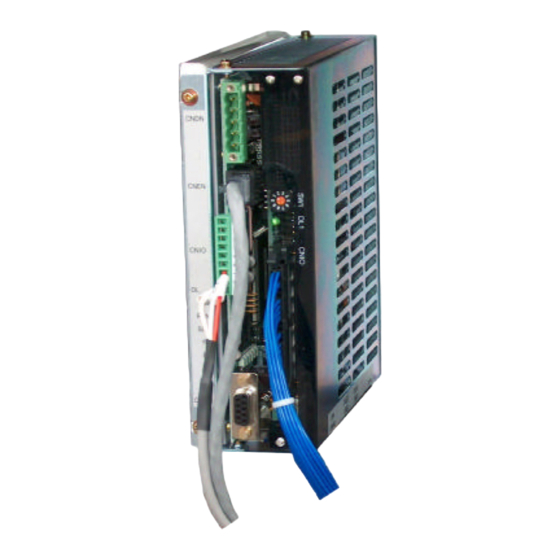
The Inverter is ready to weld (the IRTW signal is high). If the LEDs do not turn on during the weld schedule, the timer unit may be faulty, or the control may be sequencing in No Weld mode. MedWeld 5000 Technical Reference Manual 1 - 3 M-032170... - Page 22 MedWeld 5000 Overview Timer LED Indicators The timer unit in your MedWeld 5000 weld control (shown below) has indicator lights that show the current status of the weld timer. The diagrams below show the location of the status lights and what conditions cause the status lights to turn on.
-
Page 23: Devicenet Integration
The interface between the timer unit and the MFDC inverter allows the Inverter MedWeld 5000 to specify the amount of current to the work piece, allow the inverter to alert the timer of fault conditions it detects during the weld, and provides weld data to the timer, which is then displayed on the DEP. -
Page 24: Component Descriptions
MedWeld 5000 Overview Component The MedWeld 5000 control consists of the following components: Descriptions • Timer unit • Circuit breaker, • Isolation contactor, • Charging pack, • Control transformer and • MFDC Inverter. Circuit Breaker The control circuit breaker serves to remove power to the welding control and all of its internal components. -
Page 25: Control Transformer
The inverter provides the outputs to the welding transformer at H1 and H2. Timer Unit When the MedWeld 5000 timer unit receives a START WELD command, the timer unit starts executing the selected weld sequence. When the DC bus voltage stabilizes, the inverter is ready to weld. The inverter activates the IRTW signal, and the timer unit is capable of sending gating signals to the inverter. - Page 26 Inverter faults will de-energize the charging pack. Any fault shown on the DEP or any MedLAN device will inhibit the firing signal to the inverter (but does not de-energize the charging pack). 1 - 8 MedWeld 5000 Technical Reference Manual M-032170...
-
Page 27: Installing The Medweld 5000
Installing the MedWeld 5000 To install the MedWeld 5000, you must provide the required DeviceNet communications, configure the unit for the MedLAN network, set the network address and program the timer unit to meet your application requirements. These steps are described in the sections that follow. -
Page 28: Devicenet Integration
DeviceNet system must be terminated with 121 Ohms, 1%, 1/4W terminating resistors. NOTE: The MedWeld 5000 is designed to use either DeviceNet or Discrete I/O. When configuring the I/O for your application, be certain that the DeviceNet and Discrete I/O do not conflict with each other. Conflicting I/O will not allow the weld control to fire. -
Page 29: Providing Medlan Connections
BEFORE communication over the MedLAN channel is possible. Networking takes place over the MedLAN channel. Use a WTC data entry device DEP-100, or WebView for network communications or to program a single weld control. -
Page 30: Cable Routing Requirements
If the MedLAN cable must cross this wiring, it must do so at a 90° angle. Setting the timer The MedWeld 5000 uses MedLAN (WTC’s proprietary Local Area Network) to create a communications network between devices. After MedLAN Address... -
Page 31: Programming The Timer Unit
DeviceNet node address will be changed to match the port address and vise versa. Use the WTC DEP-100S to program the MedLAN address for each individual weld control, through the top (DEP) port of the timer unit. - Page 32 Installing the MedWeld 5000 All of these features are programmable from several different programming devices: • Plug the WTC DEP-100S programming device into the connector on the enclosure door or on the timer unit module. • The robot teach pendant.
-
Page 33: Flexible I/O List
- PROGRAM DISPLAY SECURITY - HEAT DISPLAY SECURITY - USER INPUT 1 - USER INPUT 2 - USER INPUT 3 - USER INPUT 4 - USER INPUT 5 - USER INPUT 6 MedWeld 5000 Technical Reference Manual 2 - 7 M-032170... - Page 34 - PRESSURE SELECT 3 - PRESSURE SELECT 4 - USER OUTPUT 1 - USER OUTPUT 2 - USER OUTPUT 3 - USER OUTPUT 4 - USER OUTPUT 5 - USER OUTPUT 6 2 - 8 MedWeld 5000 Technical Reference Manual M-032170...
- Page 35 - PROGRAM DISPLAY SECURITY - HEAT DISPLAY SECURITY - USER INPUT 1 - USER INPUT 2 - USER INPUT 3 - USER INPUT 4 - USER INPUT 5 - USER INPUT 6 MedWeld 5000 Technical Reference Manual 2 - 9 M-032170...
- Page 36 - PRESSURE SELECT 3 - PRESSURE SELECT 4 - USER OUTPUT 1 - USER OUTPUT 2 - USER OUTPUT 3 - USER OUTPUT 4 - USER OUTPUT 5 - USER OUTPUT 6 2 - 10 MedWeld 5000 Technical Reference Manual M-032170...
-
Page 37: Dep-100S Programming Device
Installing the MedWeld 5000 DEP-100S WTC’s DEP-100S Programming Device is a data entry device. Use it to program one, several or up to 30 timer units on a MedLAN network. Programming Device • When programming locally, the DEP-100S is plugged directly into the port on the WTC control. - Page 38 Installing the MedWeld 5000 2 - 12 MedWeld 5000 Technical Reference Manual M-032170...
-
Page 39: Chapter 3 Communications And I/O
The following sections describe each option and the I/O provided. Local and Safety I/O When the MedWeld 5000 is part of a network (as with the DeviceNet integration), the module provides local (discrete) control of certain critical inputs and outputs. -
Page 40: Local Outputs
SHUNT TRIP Output Activating this output trips the circuit breaker in case of a catastrophic failure. INITIATE ACKNOWLEDGE Output This output indicates that a schedule is being executed by the timer unit. 3 - 2 MedWeld 5000 Technical Reference Manual M-032170... -
Page 41: Organization Of The Devicenet I/O
(After receiving a BINARY SELECT or PARITY Inputs, the control delays for two cycles to assure that all of the desired inputs have become active.) MedWeld 5000 Technical Reference Manual 3 - 3 M-032170... - Page 42 If this input is not active when the control receives the signal to initiate a weld schedule, the timer unit generates a SYSTEM 3 - 4 MedWeld 5000 Technical Reference Manual M-032170...
- Page 43 The action of the valve depends on the status of the Retract Mode setup parameter. Caution: On power-up, it may be necessary to activate the RETRACT Input (1 or 2) to energize the output, to correct the internal state of the retract pilot. MedWeld 5000 Technical Reference Manual 3 - 5 M-032170...
- Page 44 It will also de-energize the NO FAULT output and trip the circuit breaker. ENABLE ISOLATION CONTACTOR Input This input must be active (HIGH) to enable the timer unit to activate (close) the isolation contactor. 3 - 6 MedWeld 5000 Technical Reference Manual M-032170...
- Page 45 User Inputs 1 – 8 These are generic inputs from the SLC. These inputs can be used to force the timer unit to wait in a weld schedule using the user input functions. MedWeld 5000 Technical Reference Manual 3 - 7 M-032170...
-
Page 46: Outputs
The output is used to remove power from the high-voltage circuitry when it is not required by the weld schedule. SHUNT TRIP Output This output is provided to trip the circuit breaker in case of a catastrophic failure. 3 - 8 MedWeld 5000 Technical Reference Manual M-032170... - Page 47 SureWeld steppers has reached its programmed limit. WELD IN PROGRESS Output The control turns this output ON and OFF in response to the output control function. WELD COMPLETE Output MedWeld 5000 Technical Reference Manual 3 - 9 M-032170...
- Page 48 • The SCR OVER TEMP input is closed. • When this output is activated, the RTW LED on the WTC timer unit will light. The output is de-activated when the RETRACT VALVE 1 (or 2) PILOT input is de-activated, and the setup parameter Inhibit Initiation from Retract is programmed.
-
Page 49: Devicenet Bitmap
Spare Input Spare Spare Input Spare Spare Input Spare Spare Input Spare Spare Input Spare Spare Input Spare Spare Input Spare Spare Input Spare Spare Input Spare Spare Input Spare Spare MedWeld 5000 Technical Reference Manual 3 - 11 M-032170... - Page 50 Spare Output Spare Spare Output Spare Spare Output Spare Spare Output Spare Spare Output Spare Spare Output Spare Spare Output Spare Spare Output Spare Spare Output Spare Spare Output Spare Spare 3 - 12 MedWeld 5000 Technical Reference Manual M-032170...
-
Page 51: Dep-100S Abbreviations
SYSTEM COOLING (SCR THERMAL SWITCH) Input COOL ISOLATION CONTACTOR (AUXILIARY CONTACTS) Input User Input #1 User Input #2 User Input #3 User Input #4 User Input #5 User Input #6 User Input #7 User Input #8 MedWeld 5000 Technical Reference Manual 3 - 13 M-032170... -
Page 52: Output Abbreviations
SHUNT TRIP Output INITIATE ACKNOWLEDGE Output IACK User Output #1 User Output #2 User Output #3 User Output #4 User Output #5 User Output #6 User Output #7 User Output #8 3 - 14 MedWeld 5000 Technical Reference Manual M-032170... -
Page 53: Chapter 4 Weld Schedules
Weld Schedules The MedWeld 5000 control is capable of storing up to 63 unique weld schedules. Each weld schedule can then be assigned to one of 63 independent steppers. This chapter does not describe how to create or modify a weld schedule. -
Page 54: Software Capabilities
Weld Schedules Software Capabilities The MedWeld 5000 provides commands for: • Assigning a stepper to a schedule, • Defining a linear stepper program, • Turning selected outputs on or off and • Providing weld current. Other functions enable • Overriding the setup parameters, •... -
Page 55: List Of Functions
SLOPE nn CY nnnn0 AMPS TO nnnn0 AMPS TURN ON WELD IN PROGRESS TURN OFF WELD IN PROGRESS IMPULSE = nn HEAT CY, nn COOL CY ABORT IF NO INITIATE FOR nn CYCLES REPEAT (AT NEXT FUNCTION) MedWeld 5000 Technical Reference Manual 4 - 3 M-032170... - Page 56 SEC. CURR. LIMITS: HI = nnnn0 Low=nnnn0 TRANSFORMER TURNS RATIO nnn:1 (nnn=1-256) LINEAR STEPPER #nn ASSIGNED (0 = OFF) PROCESS WELD FAULTS TURN ON ISOLATION CONTACTOR TURN OFF ISOLATION CONTACTOR GOTO SEQ #nn 4 - 4 MedWeld 5000 Technical Reference Manual M-032170...
- Page 57 TURN ON WELD IN PROGRESS TURN OFF WELD IN PROGRESS IMPULSE = nn HEAT CY, nn COOL CY ABORT IF NO INITIATE FOR nn CYCLES REPEAT (AT NEXT FUNCTION) TURN ON WELD COMPLETE MedWeld 5000 Technical Reference Manual 4 - 5 M-032170...
- Page 58 SEC. CURR. LIMITS: HI = nnnn0 Low=nnnn0 TRANSFORMER TURNS RATIO nnn:1 (nnn=1-256) LINEAR STEPPER #nn ASSIGNED (0 = OFF) PROCESS WELD FAULTS TURN ON ISOLATION CONTACTOR TURN OFF ISOLATION CONTACTOR GOTO SEQ #nn 4 - 6 MedWeld 5000 Technical Reference Manual M-032170...
-
Page 59: Function Descriptions
Experiment with the control to determine the upper and lower range of current each control can provide. WELD nn CY/IMP mm %I MedWeld 5000 Technical Reference Manual 4 - 7 M-032170... - Page 60 NOT compensate for changes in the welder secondary circuit. Caution: The Transformer Turns Ratio setup parameter must be accurately programmed for the control to supply the correct amount of secondary current in ACC firing mode. 4 - 8 MedWeld 5000 Technical Reference Manual M-032170...
-
Page 61: Weld Functions
IMPULSE= nn HEAT CY, nn COOL CY (nn=1-99) When Function appears before any weld function in a schedule, the control displays IMP (impulses) rather than CY (cycles) to indicate the weld control will pulsation weld. MedWeld 5000 Technical Reference Manual 4 - 9 M-032170... -
Page 62: Weld Functions Using Automatic Current Compensation
These functions weld, temper, pre-heat, post-heat or pre- weld. WARNING! You MUST specify the correct transformer turns ratio (especially if the welding transformer has multiple secondary taps). Obtain this data from the transformer’s rating plate or manufacturer. 4 - 10 MedWeld 5000 Technical Reference Manual M-032170... - Page 63 If the 8 millisecond blanking cycle does not complete, the operator will see "LOW LIMIT FAULT". If the MAXHEAT exceeds 40 cycles, a "HIGH LIMIT FAULT". MedWeld 5000 Technical Reference Manual 4 - 11 M-032170...
-
Page 64: Weld Functions That Adjust Current
HEAT CY, nn COOL CY (nn=1-99) appears before this function in the schedule), the timer unit gradually increases the energy provided by each impulse, until it has sloped to the desired energy. 4 - 12 MedWeld 5000 Technical Reference Manual M-032170... - Page 65 10 cycles with NO heat, and repeat this pattern 4 times. This function only affects the next function in a weld schedule. It should appear before every weld or slope function you want to pulsation weld in the schedule. MedWeld 5000 Technical Reference Manual 4 - 13 M-032170...
-
Page 66: Special Functions
This function also monitors the status of the weld initiate. When the control completes a weld schedule, it repeats the remaining functions in the schedule. At the end of the schedule, it returns to the repeat function, 4 - 14 MedWeld 5000 Technical Reference Manual M-032170... - Page 67 NOTE: The function SEC. CURR. LIMITS sets limits that are unique to a given weld schedule. The new limits override the limits programmed in the MedWeld 5000 Technical Reference Manual 4 - 15 M-032170...
- Page 68 (#0). PROCESS WELD FAULTS This function provides a one-cycle delay in the weld schedule. It asks the MedWeld 5000 to indicate any faults that may have been generated so far in the schedule. TURN ON ISOLATION CONTACTOR...
- Page 69 Caution: It is possible to create an infinite programming loop with Functions #98 (GOTO SEQ #nn IF CURRENT LESS THAN nnnn0 AMPS) and #99. MedWeld 5000 Technical Reference Manual 4 - 17 M-032170...
-
Page 70: Default Weld Sequence: Robot
TURN OFF ISOLATION CONTACTOR END OF SEQUENCE #nn NOTE: The Machine defaults were designed as a testing solution for the WTC control test department. Reloading from Machine defaults will load the WTC standard control test defaults for firing loads. WTC does not recommend using these defaults in an actual welding application. -
Page 71: Chapter 5 Advanced Software Features
A change in C-Factor will indicate changes in the welding environment. The MedWeld 5000 calculates the actual C-Factor after every weld. The programming device will display this value in its Weld Data display. C-Factor is a theoretical maximum only. It does not take into account the ratings of the weld control or transformer. -
Page 72: Dynamic Current Windows
Function #20 is WELD 10 CY 50%I • Stepper Boost is 2% • C-Factor is 170 • High Current Limit = 10% • Low Current Limit = 20%. To determine the target current: 5 - 2 MedWeld 5000 Technical Reference Manual M-032170... -
Page 73: Acc Firing Mode
= 11,700 + (1170) = 12,870 A. To determine the Low Current Limit: Low Current Limit = Target – (Target x %Low limit/100) = 11,700 – (11,700 x 20/100) = 11,700 – 2,340 = 9,360 A. MedWeld 5000 Technical Reference Manual 5 - 3 M-032170... -
Page 74: Spc Indexing Capabilities
You can then use WTC’s WebVIEW to retrieve and analyze the stored data. To perform SPC indexing, use the following functions in a weld schedule, along with the SPC setup parameters described below. -
Page 75: Spc Setup Parameters
XWSS to retrieve the data. It will then collect data for 6 more cycles (without flagging XWSS) before starting the process again. The example table on the next page is for Bin #1 ONLY. MedWeld 5000 Technical Reference Manual 5 - 5 M-032170... - Page 76 Data collected Data ignored Data collected Data ignored Data collected Data ignored NOTE: Weld Data Collection is bin dependent. Each bin has its own independent counter and is uploaded to WebVIEW separately. 5 - 6 MedWeld 5000 Technical Reference Manual M-032170...
-
Page 77: Retract Features
• Retract Mode • Initiate from Retract. WARNING! For safety, the MedWeld 5000 ignores any changes to these parameter settings until power is removed from the control. (The control checks the status of these parameters only at power-up.) Retract Mode Setup... -
Page 78: Initiation From Retract
Status allows changing the software setting at the weld processor from Weld to NoWeld. This feature is NOT supported by this version of the MedWeld 5000 software. The Display Mode does not provide the W/NW STATUS option on its display. -
Page 79: Viewing Weld Data
Regardless of the setting in the Firing Mode setup parameter, the primary current shown will be the actual primary current read from the primary current sensor. MedWeld 5000 Technical Reference Manual 5 - 9 M-032170... - Page 80 This value is used to alert the maintenance staff of a welder's deteriorating secondary or shunting conditions. The DC buss voltage at the WCU. This is updated each time the DEP-100S polls the WCU. 5 - 10 MedWeld 5000 Technical Reference Manual M-032170...
-
Page 81: Stepper Function
The primary change to the stepper operation is addition of the Tip Dress functionality. However, this version of the software also inhibits the ability to turn the stepper on or off. The software in the MedWeld 5000 does allow the stepper to be advanced or reset as needed. See the chapter on Steppers for more information. - Page 82 Advanced Software Features 5 - 12 MedWeld 5000 Technical Reference Manual M-032170...
-
Page 83: Chapter 6 Setup Parameters
Setup Parameters The MedWeld 5000 provides a number of programmable setup parameters. They allow for customizing the control to meet your application requirements. These parameters "inform" the control about its operating environment. They also define the hardware (such as the type of transformer used and its turns ratio), and describe acceptable limits on the ranges of weld parameters (such as secondary current, power factor and C-factor). -
Page 84: Parameter Descriptions
STEPPER APPROACHING MAX: (FAULT) (ALERT) (NONE) When a weld schedule is assigned to a linear stepper, this fault indicates that the stepper has begun the final step of the assigned stepper. 6 - 2 MedWeld 5000 Technical Reference Manual M-032170... - Page 85 (to cut off weld current) but the isolation contactor did NOT open. It can also occur if the isolation contactor is pulled in when a weld initiate is not present. MedWeld 5000 Technical Reference Manual 6 - 3 M-032170...
- Page 86 WIRE BREAK DETECTION: (FAULT) This fault is a function of CHC. The weld control generates this fault when input from the stainless steel wire goes low. 6 - 4 MedWeld 5000 Technical Reference Manual M-032170...
- Page 87 This fault indicates that either the energy storage capacitors on the inverter chill plate or the chill plate itself exceeded the recommended temperature. OUTPUT GROUND: (FAULT) This fault indicates a current imbalance between the two output terminals of the regulator. MedWeld 5000 Technical Reference Manual 6 - 5 M-032170...
- Page 88 This parameter controls how the inverter will supply weld current. It also sets how fault conditions will be reported if the desired amount of energy could not be delivered to the weld. 6 - 6 MedWeld 5000 Technical Reference Manual M-032170...
- Page 89 BEFORE attempting to use weld functions relating to Automatic Current Compensation mode (ACC). Setting function #81 in the weld schedule overrides this setup parameter. When programmning the control for ACC firing MedWeld 5000 Technical Reference Manual 6 - 7 M-032170...
- Page 90 For example, if the LOW HEAT LEVEL is set to 80%, when the control fires and does not reach 80% heat, the weld control will fault. HEAT CYCLE LIMIT (0=SEAM): nn (0–99) 6 - 8 MedWeld 5000 Technical Reference Manual M-032170...
- Page 91 Maximum Tip Dresses. (To disable this feature, set this parameter to zero. By default, it is set to 000.) The timer counts the number of tip dresses made and will output to the DEP when MAXIMUM TIP DRESSES has been reached. MedWeld 5000 Technical Reference Manual 6 - 9 M-032170...
- Page 92 This is the maximum speed reached by the gun as it opens after the weld is completed. MAX FORCE: (AVERAGE) (PEAK) A maximum force programmed to avoid damage to the gun mechanism. 6 - 10 MedWeld 5000 Technical Reference Manual M-032170...
-
Page 93: Default Settings
OPERATING FREQUENCY: (1200) SEC. SENSOR mV PER 1000 AMPS: (150) TRANSFORMER TURNS RATIO (50:1) PULSE WIDTH LIMIT: (99) MILLI SEC ON TIME: MILLI SEC OFF TIME: OFFSET RESISTANCE: LOW HEAT LEVEL: MedWeld 5000 Technical Reference Manual 6 - 11 M-032170... - Page 94 DATA COLLECTION SAMPLE SIZE DATA COLLECTION SAMPLE FREQUENCY (100) TRANSFORMER TURNS RATIO (100:1) NOMINAL LINE VOLTAGE (468 VOLTS) MAXIMUM TIP DRESSES VELOCITY OF CLOSE: VELOCITY OF SOFT TOUCH: VELOCITY OF OPEN: MAX FORCE: 6 - 12 MedWeld 5000 Technical Reference Manual M-032170...
-
Page 95: Chapter 7 Stepper Data
Stepper Data The MedWeld 5000 provides steppers, to help compensate for changes in the welding environment. These stepper settings are programmable, to control how the timer unit will compensate for these variations. What is a Stepper? The MedWeld 5000 provides A linear stepper type: •... -
Page 96: Linear Steppers
Counts = nnnnn setup parameter, the AUX. COUNTER AT MAX output will be turned on. This gives the operator another output to alert them to a condition without having to reset the steppers or rely on the STEPPER ALERT alone. 7 - 2 MedWeld 5000 Technical Reference Manual M-032170... -
Page 97: Default Linear Stepper Profile
This fault is generated when the stepper has completed the number of welds specified in the last step, the control resets the count to zero and generates an END OF STEPPER fault. MedWeld 5000 Technical Reference Manual 7 - 3 M-032170... -
Page 98: Display At The Dep-100S
F5, you see the stepper reset option at F3; or • Press F5 a second time to present a display showing the status of every linear stepper: • Press F5 a third time to return to the initial stepper display. 7 - 4 MedWeld 5000 Technical Reference Manual M-032170... -
Page 99: Chapter 8 Fault Conditions
Fault Conditions The fault conditions generated by the timer unit may not always identify the source of the problem. However, they do provide a starting point to begin searching. Certain conditions are defined as Faults or Alerts in the setup parameters. -
Page 100: List Of Faults
Fault Conditions List of Faults INVALID SEQUENCE SELECTED WELD INITIATE NOT PRESENT CONTROL STOP STEPPER APPROACHING MAX END OF STEPPER HIGH CURRENT LIMIT LOW CURRENT LIMIT CONTROL FAILED TO FIRE EXTEND WELD ISO CNTR OFF WHEN NEEDED ISO CNTR ERR-BRKR TRIPPED LOW C-FACTOR HIGH C-FACTOR SYSTEM COOLING... - Page 101 Fault Conditions Message Explanation Possible Cause Remedy The combination of The weld initiate was on but Turn on the BINARY SELECT Invalid BINARY SELECT no BINARY SELECT inputs input(s) required. Sequence inputs was invalid. were active. Selected The WELD INITIATE Weld schedule contains Remove Function #63 from the Weld Initiate...
- Page 102 Fault Conditions Message Explanation Possible Cause Remedy The control detected The limit is set too low. Reprogram high current limit High Current that the current fired (Function 76 SEC CURR LIM- Limit during the weld ITS). schedule exceeded Welder impedance is lower Check for improper installation the high current limit.
- Page 103 Fault Conditions Message Explanation Possible Cause Remedy The MFDC inverter Faulty cabling. (The inverter Check the timer to inverter con- Control assembly failed to fire did not receive the firing sig- nections. Verify that they are Failed to Fire for a half-cycle. nal.) secure.
- Page 104 Fault Conditions Message Explanation Possible Cause Remedy Isolation contactor The instruction to activate the Verify that the schedule Isolation was not pulled in by isolation contactor (Function contains Function #88 TURN Contactor Off the control when #88 TURN ON ISOLATION ON ISOLATION CONTAC- When required by the weld...
- Page 105 Fault Conditions Message Explanation Possible Cause Remedy The control moved Robot or PLC de- Check robot or PLC to verify Control in from Weld Mode to activated the WELD/NO that the input is being held No Weld No Weld Mode while WELD input.
- Page 106 Fault Conditions Message Explanation Possible Cause Remedy The PRESSURE Faulty robot or ladder logic. Check ladder logic to verify that Pressure SWITCH input was the input is being activated. Switch not active when Loose or incorrect wiring to Check for proper I/O designa- required by the the input module.
- Page 107 Fault Conditions Message Explanation Possible Cause Remedy BREAK- This is only used Breakthrough limit is set to Check that proper sealer was THROUGH when using the high. Too much sealer used used, check limis for break- HIGH LIMIT Breakthrough func- on the part which would bring through function tion in a welding...
- Page 108 Fault Conditions Fault Probable Cause Remedy AC line voltage is too low. (Primary Check AC power line voltage, Check LOW POWER LINE: Current and input phases for bad Primary Voltage firing modes). connections. ~or~ Three or more mid-frequency half- cycles ended due to maximum on time reached.
- Page 109 Fault Conditions The chill plate temperature exceeded Assure proper water flow to the INVERTER OVER inverter. Check chill plate tempera- TEMPERATURE: C, or the thermistor sensor on ture. Remove inverter for service if the the chill plate is open circuit. chill plate is NOT hot and the condi- tion persists.
- Page 110 Fault Conditions The Secondary Current Sensor is Check continuity of secondary current SEC CURRENT open-circuited. This condition is not sensor circuit (if used). Replace sec- SENSOR: checked if set to NONE. ondary current sensor if defective. Set this condition to NONE if no secondary current sen- sor is used.
-
Page 111: Chapter 9 Hardware Troubleshooting
Check the fuse to see if it is blown. Replace if necessary. I/O point is shorted. Inspect all I/O points for correct and secure connections. Correct and/or tighten any suspect connection(s). MedWeld 5000 Technical Reference Manual 9 - 1 M-032170... -
Page 112: Processor
If unsuccessful, replace the power supply. Controller is inoper- Defective I/O devices or Test inputs and outputs, according to the able, but no major I/O wiring. I/O Troubleshooting section. CPU faults are detected 9 - 2 MedWeld 5000 Technical Reference Manual M-032170... -
Page 113: Weld Processor
Remove power from the chassis, re- seat modules and restore power. Timer firmware incompati- Verify compatibility; correct as needed. ble. If not known, consult your WTC representative for assistance. MedWeld 5000 Technical Reference Manual 9 - 3 M-032170... - Page 114 Each control must have a be off or blinking) number. UNIQUE address. Faulty WTC timer, faulty Replace as necessary. DEP-100S or faulty Net- work Power Pack. 9 - 4 MedWeld 5000 Technical Reference Manual M-032170...
-
Page 115: Solving Typical Problems
SHUNT TRIP output on the I/O Faulty firing card or I/O module. Replace module is active when the SCR is not as necessary. shorted. Intermittent ground. Replace circuit breaker. MedWeld 5000 Technical Reference Manual 9 - 5 M-032170... - Page 116 Improper or loose wiring. Verify that connections are correct and wiring is secure. I/O designations are listed in the drawing packet provided with the control. Also check input supply voltage to the I/O module. 9 - 6 MedWeld 5000 Technical Reference Manual M-032170...
- Page 117 If NO, check the timer unit card. Replace as necessary. I/O not respond- Problem with the I/O. Check the device supplying the input or ing as expected. receiving the output. Incorrect or loose wiring to the timer unit. MedWeld 5000 Technical Reference Manual 9 - 7 M-032170...
- Page 118 Did the control weld? If NO, check the weld schedule. reading (10 A. or less) If YES, check for part fit-up, foreign material between electrodes and work piece, electrode pressure and tooling. 9 - 8 MedWeld 5000 Technical Reference Manual M-032170...
- Page 119 Re-distribute loads on the connection or weak welding bus. weld bus. Install a stiffer power supply. (On the 1,200-A. inverter, the zero- crossing signal comes through the gate board on the SCR pack.) MedWeld 5000 Technical Reference Manual 9 - 9 M-032170...
- Page 120 Hardware Troubleshooting 9 - 10 MedWeld 5000 Technical Reference Manual M-032170...
Need help?
Do you have a question about the MedWeld 5000 and is the answer not in the manual?
Questions and answers