Table of Contents

Related Manuals for Ansul CHECKFIRE 210


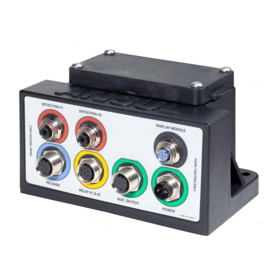
Summary of Contents for Ansul CHECKFIRE 210
- Page 1 CHECKFIRE 210 DETECTION AND ACTUATION SYSTEM OWNERS’ GUIDE © 2017 Johnson Controls. All rights reserved. All specifications and other information shown were current as of document revision date and are subject to change without notice. Part No. 442045-01...
- Page 3 Authorized ANSUL Distributors or the end user. This handbook is a quick-reference guide for basic operation of the CHECKFIRE 210 System. Two buttons on the display module and manual actuators provide operator control. Fill-In System Information (as installed)
- Page 4 IN CASE OF FIRE: Manual Actuation OPEN GUARD DOOR 009343 PUSH RED BUTTON FOR IMMEDIATE ACTIVATION 1) Safely bring equipment to complete stop, set brake and shut off engine. 2) Break visual seal and open guard door. 3) Push the red “PUSH To Activate / Alarm When Lit” button. 4) Release circuit immediately activates the connected fire suppression system (if included, pressure switch activates auxiliary operation).
- Page 5 2) Silence sounder (post discharge or fault notification) for two hours: Press and release to silence sounder; LED fault indication will continue until fault is cleared. Any new fault or detection event will reactivate sounder. 3) Reset function is for Authorized ANSUL Distributor service technician. PAGE 3...
- Page 6 Contact Authorized ANSUL Distributor for service. d. Amber pulsing 1 x 10 sec. with sounder indicates internal or external power fault. Contact Authorized ANSUL Distributor for service. e. Off indicates no system power. Contact Authorized ANSUL Distributor for service.
- Page 7 FRONT PANEL INDICATORS (Continued) STEP 2 (Continued) 009290 c. LED amber or red indications Amber: RELEASE Circuit Fault, pulsing 1 x 10 sec. DETECTION Circuit Alarm Condition, Red: pulsing 1 x 10 sec Amber: DETECTION Circuit Fault, pulsing Amber 1 x 10 sec. Red*: System DISCHARGE activated pressure switch, steady-on for remaining Release...
- Page 8 FRONT PANEL INDICATORS (Continued) 3) Red “PUSH” To Activate / Alarm When Lit” LED (sounder matches pulse rate). a. Pulsing 1 x 1 sec. indicates Pre-Alarm Condition, Alarm Only Programming or Isolate Mode. b. Pulsing 2 x 1 sec. indicates Alarm Condition and TD1 (time delay #1) starts countdown (last 5 sec.
Need help?
Do you have a question about the CHECKFIRE 210 and is the answer not in the manual?
Questions and answers