Table of Contents
Advertisement
Quick Links
Advertisement
Table of Contents

Subscribe to Our Youtube Channel
Related Manuals for Ansul CHECKFIRE 110


Summary of Contents for Ansul CHECKFIRE 110
- Page 1 CHECKFIRE 110 DETECTION AND ACTUATION SYSTEM PLANNING, INSTALLATION, OPerATION, ANd MAINTeNANCe MANUAL One Stanton Street / Marinette, WI 54143-2542, USA / +1-715-735-7411 / www.ansul.com Copyright © 2014 Tyco Fire Products LP. / All rights reserved. / Part No. 440391-03...
- Page 3 Note: The converted metric values in this manual are provided for dimensional reference only and do not reflect an actual measurement. Part Number: 440391-03 Date: 2014-AUG-28 ANSUL, CHECKFIRE, and the product names listed in this material are marks and/or registered marks. Unauthorized use is strictly prohibited.
- Page 4 CHECKFIRE 110 EXPLANATION OF SAFETY ALERTS Detection and Actuation System REV. 0 2014-APR-30 DANGER Indicates a hazardous situation in which a person will experi- ence serious personal injury or death if the situation is not avoided. WARNING Indicates a hazardous situation in which a person could expe- rience serious personal injury or death if the situation is not avoided.
- Page 5 CHECKFIRE 110 REVISION RECORD Detection and Actuation System 2014-AUG-28 REV. 02 PAGE 1 DATE PAGE REV. NO. DATE PAGE REV. NO. 2014-MAY-01 2014-MAY-08 10-1 2014-MAY-01 2014-AUG-28 FOREWORD 2014-MAY-01 2014-AUG-28 2014-MAY-01 2014-AUG-28 2014-MAY-01 2014-MAY-01 2014-MAY-01 2014-MAY-01 2014-MAY-01 2014-MAY-01 5-10 2014-MAY-01 5-11...
- Page 6 CHECKFIRE 110 REVISION RECORD Detection and Actuation System PAGE 2 REV. 0 2014-MAY-01 NOTES:...
- Page 7 CHECKFIRE 110 Connectivity The CHECKFIRE 110 Detection and Actuation System is typi- The modular cable harness system includes four color-coded cally used with an ANSUL A-101 or LVS Vehicle Fire Suppres- leads for Detection, Release, External Power, and Alarm sion System for 24-hour protection of equipment. The system Output.
- Page 8 Release Circuit Lead: Connects to a maximum of 2 Elec- TYPICAL SYSTEM CONNECTIONS tric-Pneumatic Actuators installed on agent tank expellant gas Four leads with corresponding color-coded connectors provide cartridges using Release Circuit Cable(s), Tee (needed on easy CHECKFIRE 110 System installation, see Figure 1-2. second tank), and Release Circuit Drop Cable(s). Detection Circuit Lead: Permits multiple-detection options External Power Circuit Lead: Provides a direct connection to using Detection Circuit Cable and Tees for the main detection ...
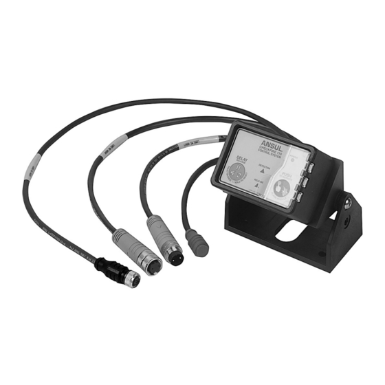
- Page 9 SECTION 2 – COMPONENTS CHECKFIRE 110 Detection and Actuation System 2014-APR-30 REV. 0 PAGE 2-1 CHECKFIRE 110 CONTROL MODULE CHECKFIRE 110/210 MOUNTING BRACKET Part No. 439559 Part No. 439564 Provides communication and control of input/output compo- Provides flexible bracket mounting of Control Module at nents. See Figure 2-1.
- Page 10 CHECKFIRE 110 SECTION 2 – COMPONENTS Detection and Actuation System PAGE 2-2 REV. 0 2014-APR-30 ELECTRIC MANUAL ACTUATOR (EMA) OPTIONAL PNEUMATIC MANUAL ACTUATOR Part No. 439400 Part No. See system manuals Provides electrical activation of the fire suppression system; Provides pneumatic actuation of the fire suppression system typically accessible from ground level and/or in a path of from a remote location typically accessible from ground level egress. See Figure 2-4. and/or in a path of egress. ...
- Page 11 SECTION 2 – COMPONENTS CHECKFIRE 110 Detection and Actuation System 2014-MAY-08 REv. 01 PAGE 2-3 SPOT THERMAL DETECTOR LINEAR DETECTOR Part No. See Temperature Selections Table Part No. See table Provides spot thermal detection in the protected area(s). See Provides fire detection in the protected area; connects to the Figure 2-6. CHECkFIRE 110 Control Module via the Detection Circuit Cable. See Figure 2-8. • C olor-coded fixed-temperature design • R ed color-coded connectors • ...
- Page 12 CHECKFIRE 110 SECTION 2 – COMPONENTS Detection and Actuation System PAGE 2-4 REv. 01 2014-MAY-01 DETECTION CIRCUIT CABLE DETECTION CIRCUIT TEE Part No. See table Part No. 439394 Connects to CHECkFIRE 110 Control Module, Electric Manual Connects individual Electric Manual Actuator(s) or Spot Actuator(s) (EMA), and detection input components. See Thermal Detector(s) to main detection circuit trunk. See Figure 2-9. Figure 2-11. • I P67 connectors • ...
- Page 13 SECTION 2 – COMPONENTS CHECKFIRE 110 Detection and Actuation System 2014-MAY-01 REv. 01 PAGE 2-5 RELEASE CIRCUIT CABLE RELEASE CIRCUIT DROP CABLE Part No. See table Part No. See table Connects to CHECkFIRE 110 Control Module, Release Circuit Provides connectivity between Release Circuit Cable and Elec- Tee, and/or Release Circuit Drop Cable(s). See Figure 2-14. tric-Pneumatic Actuator. See Figure 2-16. • I P67 connectors • I P67 connectors ...
- Page 14 CHECKFIRE 110 SECTION 2 – COMPONENTS Detection and Actuation System PAGE 2-6 REv. 0 2014-APR-30 ELECTRIC-PNEUMATIC ACTUATOR PROTRACTING ACTUATION DEVICE (PAD) (Continued) Part No. 439569 (normally supplied with agent tanks or • G enerates force to drive the Electric-Pneumatic Actuator expellant gas cartridge/bracket assemblies) puncture pin through an expellant gas cartridge seal, ...
- Page 15 SECTION 2 – COMPONENTS CHECKFIRE 110 Detection and Actuation System 2014-MAY-01 REv. 01 PAGE 2-7 POWER CIRCUIT CABLE FUSED POWER CIRCUIT CABLE Part No. See table Part No. 439492 Connects CHECkFIRE 110 Control Module to Fused Power Connects Power Circuit Cable to the 12/24 vDC vehicle power Circuit Cable. See Figure 2-23. source. See Figure 2-24. • I P67 connectors • ...
- Page 16 CHECKFIRE 110 SECTION 2 – COMPONENTS Detection and Actuation System PAGE 2-8 REv. 0 2014-APR-30 LABEL PACKAGE As a reminder to service and maintenance personnel, install Part No. 440798 this CAUTIon (Label no. 71455) in the area protected by the Linear Detector. See Figure 2-28. Provides instructions for vehicle operators and service person- nel on system operation and protection. Attach appropriate labels as needed in the specified locations. See Figures 2-26 thru 2-29. If automatic vehicle shutdown is part of the CHECkFIRE System, install Label no. 440799 near the operator’s line of vision. Cut out the correct time delay value from Label no. 440800, remove backing to expose adhesive, and attach to Label 440799 in the space provided. See Figure 2-26. FIGURE 2-28 LABEL FOR PROTECTING LINEAR DETECTOR 009325 Install this label next to every Electric Manual Actuator (EMA). ...
- Page 17 SECTION 2 – COMPONENTS CHECKFIRE 110 Detection and Actuation System 2014-MAY-08 REv. 02 PAGE 2-9 VEHICLE SYSTEM PRESSURE SWITCH To vEHICLE Part No. 440090 ConnECTIonS Provides auxiliary functions (i.e., equipment shutdown, turning on notification appliances, or providing “Pressure Switch Feedback” to a vehicle control panel). See Figure 2-30. • o ne integral cable, sealed to switch housing • M anually resettable 3-conductor (no/C/nC) SPDT switch • R ated for 6A with 12/36 vDC nominal • I ncludes Pressure Switch Connector kit (Part no. 440086) to ...
- Page 18 CHECKFIRE 110 SECTION 2 – COMPONENTS Detection and Actuation System PAGE 2-10 REV. 0 2014-APR-30 DETECTION CIRCUIT TESTER RELEASE CIRCUIT TESTER Part No. 440097 Part No. 441021 Simulates normal, fault, and alarm conditions for testing the Indicates a successful release energy pulse to fire the PAD CHECkFIRE 110 Control Module performance. See Figure (pass or fail). See Figure 2-33. 2-32. Switch settings: SWITCH: oFF, normal on, RESET Fault Alarm FIGURE 2-32...
- Page 19 PAGE 3-1 USER INTERFACE CONTROL MODULE FRONT PANEL BUTTONS This section provides the user with overall information on “DELAY/Reset/Silence” Button features and operation of the CHECKFIRE 110 Control Manage fault and/or detection conditions by pressing the Module. “DELAY/Reset/Silence” button (See Figure 3-2) for the follow- ing results: FIELD CONNECTIVITY –...
- Page 20 CHECKFIRE 110 SECTION 3 – USER INTERFACE Detection and Actuation System PAGE 3-2 REV. 01 2014-MAY-01 CONTROL MODULE FRONT PANEL BUTTONS (Continued) 2. P ulses RED, 4 x1 second in the final 5 seconds until time delay has expired (sounder matches pulse rate). Red “PUSH To Activate / Alarm When Lit” Button and LED ...
- Page 21 In the event primary power source is low or disconnected pulse rate for 10 minutes, then auto-silences to conserve the CHECKFIRE 110 Control Module has an internal reserve energy power source providing up to 72 hours of reserve power. A low • ...
- Page 22 CHECKFIRE 110 SECTION 3 – USER INTERFACE Detection and Actuation System PAGE 3-4 REV. 0 2014-APR-30 NOTES:...
- Page 23 Individuals responsible for planning (or designing) a CHECK- FIRE 110 Detection and Actuation System must hold current • P lastic parts ANSUL Certification from an ANSUL A-101 and/or LVS train- • r ubber ing program. In addition to the certification, planners must • ...
- Page 24 For safety, evacuate the vehicle at the earliest lVs Manual (Part No. 427109) possible moment. The control module pulsing lEDs and 85 dB sounder are intended to alert the operator when the unit receives a fault CHECKFIRE 110 Circuit Cable Leads and Cable signal or detection input from a detection device (before actuat- Assemblies ing the fire suppression system). Plan on routing circuit cable assemblies in accessible loca- The Alarm Circuit 3.3 VDC digital output from the control ...
- Page 25 SECTION 4 – SYSTEM PLANNING CHECKFIRE 110 Detection and Actuation System 2014-MAY-01 rEV. 01 PAGE 4-3 Detection Circuit Cable (Red Connectors) Connects input devices to the CHECKFIRE 110 Control Module such as: • E lectric Manual Actuators (EMA) • l inear Detectors • s pot Thermal Detectors 1.
- Page 26 CHECKFIRE 110 SECTION 4 – SYSTEM PLANNING Detection and Actuation System PAGE 4-4 rEV. 01 2014-MAY 01 Detection Circuit Cable (Red Connectors) (Continued) DEVICE lINEAr DETECTOr linear Detector (red connectors and twisted cable) connects BEND rADIUs directly to the main Detection Circuit Cable. NOT lEss THAN 2.5 IN. (64 mm) • ...
- Page 27 SECTION 4 – SYSTEM PLANNING CHECKFIRE 110 Detection and Actuation System 2014-APr-30 rEV. 0 PAGE 4-5 Detection Circuit Cable (Red Connectors) (Continued) INCOrrECT DEsIGN INsTAllATIONs sPOT THErMAl DETECTOr sElECTION AND PlACE- CAUTION MENT (Continued) 3. Connect directly to Detection Circuit Cable or connect to Do not use an EOL Device on a branch because the complete Linear Detector assemblies.
- Page 28 CHECKFIRE 110 SECTION 4 – SYSTEM PLANNING Detection and Actuation System PAGE 4-6 rEV. 01 2014-MAY-01 Detection Circuit Cable (Red Connectors) (Continued) Release Circuit Cable (Blue Connectors) INCOrrECT DEsIGN INsTAllATIONs (Continued) Connects Electric-Pneumatic Actuator(s) (for agent tank expel- lant gas cartridges(s)) to CHECKFIrE 110 Control Module. ...
- Page 29 SECTION 4 – SYSTEM PLANNING CHECKFIRE 110 Detection and Actuation System 2014-AUG-28 rEV. 02 PAGE 4-7 Power Circuit Cables (Green Connectors) Vehicle System Pressure Switch Connects CHECKFIrE 110 Control Module to 12/24 VDC The Vehicle system Pressure switch is a manually resettable nominal vehicle power source using the Power Circuit Cable 4-conductor sPDT switch, rated for 6A when used with volt- and the Fused Power Circuit Cable (connects to vehicle power ages between 12 VDC and 36 VDC nominal. The switch can supply). be used to perform several different tasks on system actuation, including equipment shutdown, turning on notification appli-...
- Page 30 CHECKFIRE 110 SECTION 4 – SYSTEM PLANNING Detection and Actuation System PAGE 4-8 rEV. 0 2014-APr-30 COMPONENTS PLANNING CHECKLIST h CHECKFIrE 110 Control Module h M ounting Bracket h D etection Circuit Cable(s), Tees, EOl Device, and Branch Terminator(s) h E lectric Manual Actuator(s) (EMA) and Bracket(s) h Linear Detector(s) h ...
- Page 31 AND THREADED BOSS CHECKFIRE 110 CONTROL MODULE INSTALLATION FIGURE 5-1 SURFACE MOUNTING TEMPLATE The CHECKFIRE 110 Control Module may be surface (FOAM GASKET) mounted (3/16 in. (4.7 mm) maximum thickness) or bracket 009203 mounted. For bracket mounting, use the CHECKFIRE 110/210 Mounting Bracket (Part No.
- Page 32 Surface Mounting Instructions (Continued) Bracket Mounting Instructions 8. Hand-tighten enclosure nut on threaded boss, see Figure Bracket mounting requires the CHECKFIRE 110/210 Mount- 5-3. ing Bracket (Part No. 439564). The bracket is a two piece, multi-position bracket for securing the control module in a variety of configurations.
- Page 33 6. Attach control module to swivel mount according to the position determined in Step 1. a. Retrieve enclosure nut and rubber washer for threaded boss from separate bag in the CHECKFIRE 110 Ship- ping Assembly (Part No. 439559). b. Carefully feed cables through center hole in Swivel Mount, rubber washer, and enclosure nut.
- Page 34 REV. 0 2014-APR-30 Bracket Mounting Instructions (Continued) CABLE CONNECTIVITY / INSTALLATION The CHECKFIRE 110 System utilizes IP67 circular threaded CAUTION connectors on all cable and tee components. This modular cable harness reduces installation time and damaged cables The enclosure nut should only be hand-tightened, do not use can be replaced without replacing the entire cable assembly.
- Page 35 SECTION 5 – INSTALLATION CHECKFIRE 110 Detection and Actuation System 2014-MAY-01 REV. 01 PAGE 5-5 Connector Assembly (Continued) 2. Lightly press connectors together while rotating until the CORRECT: RUBBER-COATED keys align. Then firmly press connectors together while 5/16 IN. (8 mm) P-CLAMP threading swivel nut;...
- Page 36 BULKHEAD CONNECTOR BULKHEAD CONNECTOR 1. Make sure detection circuit cable is completely installed FIGURE 5-14 from CHECKFIRE 110 Control Module to hazard area end BULKHEAD CONNECTORS point. Start installation of Linear Detector at end point of detection circuit cable. 009159 / 009166 2.
- Page 37 SECTION 5 – INSTALLATION CHECKFIRE 110 Detection and Actuation System 2014-MAY-08 REV. 02 PAGE 5-7 LINEAR DETECTOR INSTALLATION (Continued) SPOT THERMAL DETECTOR INSTALLATION Mount in a location where detector head points in a downward position with exposure over the hazard area (refer to layout drawing).
- Page 38 CHECKFIRE 110 SECTION 5 – INSTALLATION Detection and Actuation System PAGE 5-8 REV. 0 2014-APR-30 SPOT THERMAL DETECTOR INSTALLATION (Continued) EMA may be surface (1/4 in. (6.3 mm) maximum thickness) or bracket mounted. For bracket mounting use the EMA Bracket RETAINING NUT (Part No.
- Page 39 RUBBER see Figure 5-26. Do not bend or remove the Preventor; it is wASHER required for correct operation of the actuator. The CHECKFIRE 110 Control Module can actuate a maximum of two Electric-Pneumatic Actuators. FIGURE 5-22 EMA SURFACE MOUNT INSTALLED...
- Page 40 Cable Connectivity / Installation, PREVENTOR page 5-4. SLIDES UNDER THREADS PREVENTOR COLOR CHANGED FOR CLARITY FIGURE 5-27 SLIDE ACTUATOR ONTO CARTRIDGE NOTE: CABLES SHOwN 009221 SHORTER THAN ACTUAL LENGTH DETECTION CIRCUIT LEAD FIGURE 5-29 CHECKFIRE 110 CABLES 009150...
- Page 41 SECTION 5 – INSTALLATION CHECKFIRE 110 Detection and Actuation System 2014-MAY-01 REV. 01 PAGE 5-11 DETECTION CIRCUIT CABLES (Continued) 4. The Linear Detector may be installed anywhere in the main detection circuit trunk after the EMA. If the last device, the Verify cable route from the control module to the detection Linear Detector is terminated with an EOL Device.
- Page 42 CHECKFIRE 110 SECTION 5 – INSTALLATION Detection and Actuation System PAGE 5-12 REV. 01 2014-MAY-01 DETECTION CIRCUIT CABLES (Continued) CAUTION INCORRECT INSTALLATIONS Install EMA(s) as the first component(s) on the Detection Circuit CAUTION and on a single use branch. Failure to comply may cause the system to not function properly.
- Page 43 SHORTER THAN ACTUAL LENGTH RELEASE CIRCUIT LEAD wITH DUST CAP FIGURE 5-40 FIGURE 5-41 CHECKFIRE 110 CABLES RELEASE CIRCUIT - TWO TANKS 009150 009225 Install Release Circuit using the following rules (see Figure 5-41 and 5-42): CAUTION 1. Maximum two PADs.
- Page 44 “+ VEH BATT” to the positive post on The Power Circuit Cable Lead (Green connector) on the the battery or 12/24 VDC nominal power source. Do not CHECKFIRE 110 Control Module is the starting point of the install fuse at this time. power circuit. See Figure 5-43.
- Page 45 (see Figure 5-47): The Digital 3.3 VDC Alarm Output Circuit Lead (Yellow plug) on the CHECKFIRE 110 Control Module is an 18 AwG, two 1. The pressure switch installs in a standard 1/4 in. NPT conductor polarity sensitive cable assembly. The white conduc- female fitting.
- Page 46 CHECKFIRE 110 SECTION 5 – INSTALLATION Detection and Actuation System PAGE 5-16 REV. 0 2014-APR-30 VEHICLE SYSTEM PRESSURE SWITCH (Continued) e. Using the supplied 22-18AwG Butt Splice Terminals, crimp the splices onto each pressure switch wire Pressure Switch Reset being used. Once complete, crimp the splices to the 2.
- Page 47 SECTION 5 – INSTALLATION CHECKFIRE 110 Detection and Actuation System 2014-APR-30 REV. 0 PAGE 5-17 LABEL PACKAGE As a reminder to service and maintenance personnel, install Part No. 440798 this CAUTION (Label No. 71455) in the area protected by the Linear Detector.
- Page 48 CHECKFIRE 110 SECTION 5 – INSTALLATION Detection and Actuation System PAGE 5-18 REV. 0 2014-APR-30 FINAL CONNECTIONS Electric actuation: Refer to Section 6 – Test and Place in Service for final electric actuation connections. Combined electric and pneumatic actuation: Connect both...
- Page 49 SECTION 6 – TEST AND PLACE IN SERVICE CHECKFIRE 110 Detection and Actuation System 2014-MAY-01 REV. 01 PAGE 6-1 CAUTION Before performing any operational test(s), protect the fire suppression system from uninten- tional actuation. Verify Electric-Pneumatic Actuators are not connected to Release Circuit Drop Cables and any pneumatic manual actuators are ring-pinned for safety and/or actua- tion cartridges removed.
- Page 50 Before conducting the OPERATIONAL TEST, make certain CONFIRM INLINE FuSE RED TO POSITIVE (+) CONNECTIONS HOLDER external power is properly connected to CHECKFIRE 110 BATTERY POST Control Module (see Section 5 - Installation, page 5-14). • I f fuse is not installed, follow instructions in Section 5 – 009173 Installation, page 5-14 (step 5).
- Page 51 Detection and Actuation System 2014-APR-30 REV. 0 PAGE 6-3 TABLE 6-2: ISOLATION FEATURE (Continued) Place the CHECKFIRE 110 Control Module in Isolate Mode PLACE IN ISOLATE mODE then confirm: system will not auto release and will manually actuate while in Isolate Mode.
- Page 52 CHECKFIRE 110 SECTION 6 – TEST AND PLACE IN SERVICE Detection and Actuation System PAGE 6-4 REV. 0 2014-APR-30 TABLE 6-2: ISOLATION FEATURE (Continued) 7. Post Release Activated – the Red “PUSH to Activate / POST RELEASE Alarm When Lit” LED and sounder pulse 1 x 10 seconds;...
- Page 53 Note: The release time delay only applies to a detec- tion device input. The time delay is bypassed when the CHECKFIRE 110 Control Module or an EMA is manually actuated. Options for the release time delay are either 5 seconds or 15...
- Page 54 DETECTION FAULT Detection Circuit - Supervision Test INDICATION (DCT SwITCH = FAULT) Set DCT switch to “Fault” position. The CHECKFIRE 110 Control Module indicates the following: 1. Detection Fault LED pulses AMBER 1 x 10 seconds. AMBER LED AND SOuNDER 2.
- Page 55 CONTINuES) AMBER LED PuLSES 1 x 10 SECONDS 009180b Reconnect RCT to release circuit. RECONNECT RCT 4. CHECKFIRE 110 Control Module returns to Normal status; Power LED is GREEN steady-on. MODuLE RETuRNS TO NORMAL STATuS POWER LED IS GREEN STEADY-ON...
- Page 56 RECONNECT 4. Reconnect external power circuit connection at the ExTERNAL POWER AND MODuLE Power Circuit Lead. The CHECKFIRE 110 Control RETuRNS TO Module returns to Normal status; Power LED is GREEN NORMAL STATuS steady-on. (may take up to 10 seconds)
- Page 57 SECTION 6 – TEST AND PLACE IN SERVICE CHECKFIRE 110 Detection and Actuation System 2014-APR-30 REV. 0 PAGE 6-9 TABLE 6-4: OPERATIONAL TEST (Continued) Detection Circuit: Alarm Condition Test CAUTION VERIFY RCT AND DCT CAUTION INSTALLED! Before beginning this test, verify: • ...
- Page 58 CHECKFIRE 110 SECTION 6 – TEST AND PLACE IN SERVICE Detection and Actuation System PAGE 6-10 REV. 0 2014-APR-30 TABLE 6-4: OPERATIONAL TEST (Continued) Detection Circuit: Test Time Delay Restart RETURN TO NORmAL STATUS 1. Reset DCT to normal position.
- Page 59 SECTION 6 – TEST AND PLACE IN SERVICE CHECKFIRE 110 Detection and Actuation System 2014-APR-30 REV. 0 PAGE 6-11 TABLE 6-4: OPERATIONAL TEST (Continued) manual Activation Release Circuit Test mANUAL ACTIVATION 1. Open the protective guard door and push the “PuSH to Activate / Alarm When Lit”...
- Page 60 CHECKFIRE 110 SECTION 6 – TEST AND PLACE IN SERVICE Detection and Actuation System PAGE 6-12 REV. 0 2014-APR-30 TABLE 6-4: OPERATIONAL TEST (Continued) Field Test Spot Thermal Detectors This field test procedure is not intended to determine the exact operating temperature of any detector. It is designed to test functionality only.
- Page 61 4. Continue to apply heat to the detector head until contact closure occurs. An audible click should be heard from the detector head and the CHECKFIRE 110 Control Module HEAT GuN should go into alarm. Note: Reaction times between detectors will vary.
- Page 62 CHECKFIRE 110 SECTION 6 – TEST AND PLACE IN SERVICE Detection and Actuation System PAGE 6-14 REV. 0 2014-APR-30 TABLE 6-4: OPERATIONAL TEST (Continued) Electric manual Actuator (EmA) Test PuLL RING PIN AND STRIKE RED BuTTON CAUTION 10 SECOND RELEASE STARTS...
- Page 63 Release Fault Indicator does not pulse. TABLE 6-6: INTERNAL POwER CIRCUIT – OPERATIONAL TEST Disconnect external power circuit connection at the INTERNAL POwER TESTING (REmOVE CHECKFIRE 110 Power Circuit Lead. POwER CABLE) 1. Power LED pulses AMBER 1 x 30 seconds. AMBER POWER LED AND 2.
- Page 64 Detection and Actuation System PAGE 6-16 REV. 0 2014-APR-30 TABLE 6-7: PLACING CHECKFIRE 110 CONTROL mODULE IN SERVICE 1. Reconnect external power circuit. The Power LED returns to GREEN steady-on. (At completion of testing return all devices to normal status.)
- Page 65 Detection and Actuation System 2014-APR-30 REV. 0 PAGE 6-17 TABLE 6-7: PLACING CHECKFIRE 110 CONTROL mODULE IN SERVICE (Continued) 6. Remove actuator cap on top of Electric-Pneumatic Actua- tor and retain for future use. REMOVE Before installing PAD(s) place control module in ACTuATOR CAP Isolate mode, see Table 2 –...
- Page 66 SECTION 6 – TEST AND PLACE IN SERVICE Detection and Actuation System PAGE 6-18 REV. 0 2014-APR-30 TABLE 6-7: PLACING CHECKFIRE 110 CONTROL mODULE IN SERVICE (Continued) 9. If needed complete installation of optional pneumatic manual actuator(s). Refer to Section 5 – Installation. ELECTRONIC ACTuATION INSTALLATION COMPLETE 10.
- Page 67 All equipment operators or anyone who If the “DELAY/Reset/Silence” button (on the control module) has any responsibility for the equipment should understand is pushed and released before the end of time delay cycle how the CHECKFIRE 110 Electric Detection and Actuation (5 or 15 seconds), the time delay repeats the delay cycle, System operates. Every operator should be completely trained delaying eventual system discharge and pressure switch oper- in these procedures.
- Page 68 CHECKFIRE 110 SECTION 7 – IN CaSE Of fIrE Detection and Actuation System PAGE 7-2 REV. 0 2014-APR-30 NOTES:...
- Page 69 Individuals responsible for recharging, inspecting, and main- diate area(s) of fire must be replaced. When subject taining a CHECKFIRE 110 System, must hold current ANSUL to high temperatures, set-point drift and damage may Certification from an ANSUL A-101 or LVS training program.
- Page 70 CHECKFIRE 110 SECTION 8 – RECHARGE, INSPECTION, AND MAINTENANCE Detection and Actuation System PAGE 8-2 REV. 01 2014-MAY-01 RECHARGE (Continued) c. Examine actuating end of PAD to determine if PAD has actuated. Note: Occasionally the actuating pin will pull RELEASE back into the PAD.
- Page 71 REV. 01 PAGE 8-3 RECHARGE (Continued) INSPECTION AND MAINTENANCE To help ensure the CHECKFIRE 110 Detection and Actuation PIN NOT RETRACTED PIN COMPLETELY RETRACTED System will operate as intended, proper inspection and mainte- nance procedures must be performed at the specified intervals.
- Page 72 CHECKFIRE 110 SECTION 8 – RECHARGE, INSPECTION, AND MAINTENANCE Detection and Actuation System PAGE 8-4 REV. 0 2014-APR-30 MAINTENANCE (Continued) 6. Check and perform maintenance on each Electric-Pneu- matic Actuator (Part No. 439569) (installed on each agent 2. Check cable connectivity and integrity.
- Page 73 10. Confirm all system equipment has been properly serviced and recharged, and visual inspection seals are in place on all EMAs and CHECKFIRE 110 Control Module. 11. Record date of maintenance on tag and in permanent record file. Notify operating personnel system is back in...
- Page 74 4. Place in service by completing Table 7 – Placing discarding. Actuate the PAD in a safe manner consis- CHECKFIRE 110 Control Module in Service, pages 6-13 – tent with site safety policies. 6-15 (Section 6 – Test and Place in Service).
- Page 75 PAGE 9-1 TROUBLESHOOTING The following tables provide information on normal operating and fault condition indications for the CHECKFIRE 110 Detection and Actuation System. Refer to Table 5 for detailed circuit testing procedures. When all faults are cleared, confirm proper operation of the entire CHECKFIRE 110 System by completing Section 6 - Test and Place in Service.
- Page 76 CHECKFIRE 110 SECTION 9 – TROUBLESHOOTING Detection and Actuation System PAGE 9-2 REV. 0 2014-APR-30 TABLE 9-2: RELEASE CIRCUIT FAULT Release Circuit Fault Release Circuit Fault LED and Sounder pulsing 1 x 10 seconds indicating Release Circuit Fault. RELEASE CIRCUIT FAULT PULSING • ...
- Page 77 PAGE 9-3 TABLE 9-3: DETECTION CIRCUIT FAULT (Continued) Isolate Mode Condition Detection Circuit Fault LED and Sounder pulsing quickly DETECTION 2 x 30 seconds indicate CHECKFIRE 110 Control Module is CIRCUIT FAULT – ISOLATION MODE in ISOLATE MODE. PULSING qUICKLY Placing the control module in Isolate Mode minimizes occur-...
- Page 78 Note: Once all faults are cleared, confirm proper operation of the entire CHECKFIRE 110 System by completing Section 6 - Test and Place in Service. If faults cannot be cleared, test each circuit and cable individ-...
- Page 79 Power Circuit Cable. If voltage on Power Circuit Cable is correct, there is a control module internal problem and the CHECKFIRE 110 Control Module must be replaced. 2. If voltage on Power Circuit Cable is not correct, use the FOLLOW SECTION 5 –...
- Page 80 Control Module. Power LED returns to GREEN steady-on. If all faults are clear, verify proper operation of the CHECKFIRE 110 System by completing Section 6 – Test and Place in Service. Note: Specific jurisdictions or customer procedures may require documentation of all components replaced.
- Page 81 REV. 01 PAGE 9-7 TABLE 9-5: SPECIFIC CIRCUIT TESTING PROCEDURES (Continued) Release Circuit (Continued) 2. If Release Circuit Fault clears, the CHECKFIRE 110 2. IF FAULT CLEARS, RECONNECT AND COMPLETE SDR Control Module is functioning properly. Re-install complete release circuit to the control module release circuit lead 3.
- Page 82 If all faults are clear, verify proper operation of the CHECKFIRE 110 System by completing Section 6 – Test and Place in Service. Note: Specific jurisdictions or customer procedures may require documentation of all components replaced.
- Page 83 If all faults are clear, verify proper operation of the CHECKFIRE 110 System by completing Section 6 – Test and Place in Service. Note: Specific jurisdictions or customer procedures may require documentation of all components replaced. Keep a...
- Page 84 CHECKFIRE 110 SECTION 9 – TROUBLESHOOTING Detection and Actuation System PAGE 9-10 REV. 0 2014-APR-30 NOTES:...
- Page 85 PAGE 10-1 COMPONENT INDEX Part No. Description Part No. Description System Components Accessory Equipment 439559 Control Module, CHECKFIRE 110 438280 Spot Thermal Detector, 250 °F (121 °C) 439564 Mounting Bracket, CHECKFIRE 110/210 438281 Spot Thermal Detector, 350 °F (177 °C)
- Page 86 CHECKFIRE 110 SECTION 10 – APPENDIX Detection and Actuation System PAGE 10-2 REV. 0 2014-APR-30 CAbLE AND buLkhEAD DIMENSIONS Largest hole Size to Cable Type Diameter Cable Diameter Pass Connector Images on Connector Through (mm) (mm) (mm) Linear Detector 0.64 (16.3)
- Page 87 SECTION 10 – APPENDIX CHECKFIRE 110 Detection and Actuation System 2014-APR-30 REV. 0 PAGE 10-3 LINEAR DETECTOR FLuID RESISTANCE CAPAbILITY Resistance Rating Key: G = GOOD L = LIMITED C = CONDITIONAL (Service conditions must be outlined to Tyco Fire Protection Products for approval of cable suitability for applications.)
- Page 88 CHECKFIRE 110 SECTION 10 – APPENDIX Detection and Actuation System PAGE 10-4 REV. 0 2014-APR-30 ChEMICAL RESISTANT ChART (For Linear Detector material) This chemical resistance chart cannot predict the effect on the outer covering to complex chemical mixtures. The appropriate...
Need help?
Do you have a question about the CHECKFIRE 110 and is the answer not in the manual?
Questions and answers