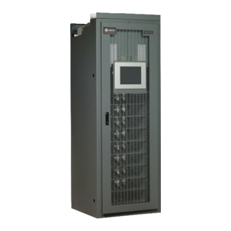
Vertiv NetSure 7200 Series Installation Manual
Return bus load shunt monitoring cable assembly kit
Hide thumbs
Also See for NetSure 7200 Series:
- Installation manual (118 pages) ,
- User manual (40 pages)
Subscribe to Our Youtube Channel
Summary of Contents for Vertiv NetSure 7200 Series
- Page 1 Return Bus Load Shunt Monitoring Cable Assembly Kit Installation Manual Kit Specification Number: 559404 For Use in Spec. No. 582127200 Power Systems...
- Page 2 The information contained in this document is subject to change without notice and may not be suitable for all applications. While every precaution has been taken to ensure the accuracy and completeness of this document, Vertiv assumes no responsibility and disclaims all liability for damages resulting from use of this information or for any errors or omissions.
-
Page 3: Table Of Contents
Safety Admonishments Definitions ............................................v Safety and Regulatory Statements ............................................v Déclarations de Sécurité et de Réglementation ......................................v 1 Vertiv™ Return Bus Load Shunt Monitoring Cable Assembly Kit ..............1 1.1 Kit Description ....................................................1 1.2 Kit Contents ......................................................1 1.3 Tools and Material Required ............................................... -
Page 4: Admonishments Used In This Document
Vertiv™ Return Bus Load Shunt Monitoring Cable Assembly Kit Installation Manual Admonishments Used in this Document will likely DANGER! Warns of a hazard the reader be exposed to that will result in death or serious injury if not avoided. (ANSI, OSHA) -
Page 5: Important Safety Instructions
Vertiv™ Return Bus Load Shunt Monitoring Cable Assembly Kit Installation Manual Important Safety Instructions Safety Admonishments Definitions Definitions of the safety admonishments used in this document are listed under “Admonishments Used in this Document” on page iv. Safety and Regulatory Statements Refer to Section 4154 (provided with your customer documentation) for Safety and Regulatory Statements. - Page 6 Vertiv™ Return Bus Load Shunt Monitoring Cable Assembly Kit Installation Manual This page intentionally left blank. Proprietary and Confidential © 2022 Vertiv Group Corp.
-
Page 7: Vertiv™ Return Bus Load Shunt Monitoring Cable Assembly Kit
Vertiv™ Return Bus Load Shunt Monitoring Cable Assembly Kit Installation Manual 1 Vertiv™ Return Bus Load Shunt Monitoring Cable Assembly 1.1 Kit Description These instructions provide a step-by-step procedure to field install this kit into Power System Spec. No. 582127200. Installation of this kit in other equipment should not be attempted. - Page 8 Vertiv™ Return Bus Load Shunt Monitoring Cable Assembly Kit Installation Manual NOTE! When performing any step in this procedure which requires removal of existing hardware, retain all hardware for use in subsequent steps, unless otherwise stated. 1.4.1 Procedure DANGER! Observe the Important Safety Instructions located at the beginning of this document.
- Page 9 Vertiv™ Return Bus Load Shunt Monitoring Cable Assembly Kit Installation Manual Figure 1.1 Installing the Kit SM-DU SM-DU Shunt Input Terminal Block Board Disconnect this connector. Place kit supplied wire harness pigtail between Primary Power Bay the two connectors just separated.
-
Page 10: Sm-Du External Shunt Connections
Vertiv™ Return Bus Load Shunt Monitoring Cable Assembly Kit Installation Manual 2 SM-DU External Shunt Connections You just installed wire harness pigtail P/N 559353 that was included in kit P/N 559404. This allows you to connect external shunts which are located in the return bus to the SM-DU module. The SM-DU module provides five (5) shunt monitoring inputs. Refer to the following procedure and Figure 2.1 for connections details. - Page 11 Vertiv™ Return Bus Load Shunt Monitoring Cable Assembly Kit Installation Manual Figure 2.1 External Shunt Connections to the SM-DU Module SM-DU Shunt Input Wire Size Capacity: Terminal Block 22-12 AWG. Torque: 6 in-lbs. + - + - + - + - + -...
- Page 12 Vertiv™ Return Bus Load Shunt Monitoring Cable Assembly Kit Installation Manual This page intentionally left blank. Proprietary and Confidential © 2022 Vertiv Group Corp.
- Page 13 Vertiv™ Return Bus Load Shunt Monitoring Cable Assembly Kit Installation Manual Connect with Vertiv on Social Media https://www.facebook.com/vertivI https://www.instagram.com/vertiv/ https://www.linkedin.com/company/vertiv/ https://www.twitter.com/vertiv/ Proprietary and Confidential © 2022 Vertiv Group Corp.
- Page 14 Vertiv.com | Vertiv Headquarters, 1050 Dearborn Drive, Columbus, OH, 43085, USA © 2022 Vertiv Group Corp. All rights reserved. Vertiv™ and the Vertiv logo are trademarks or registered trademarks of Vertiv Group Corp. All other names and logos referred to are trade names, trademarks or registered trademarks of their respective owners. While every precaution has been taken to ensure accuracy and completeness here, Vertiv Group Corp.


Need help?
Do you have a question about the NetSure 7200 Series and is the answer not in the manual?
Questions and answers