Table of Contents
Advertisement
Quick Links
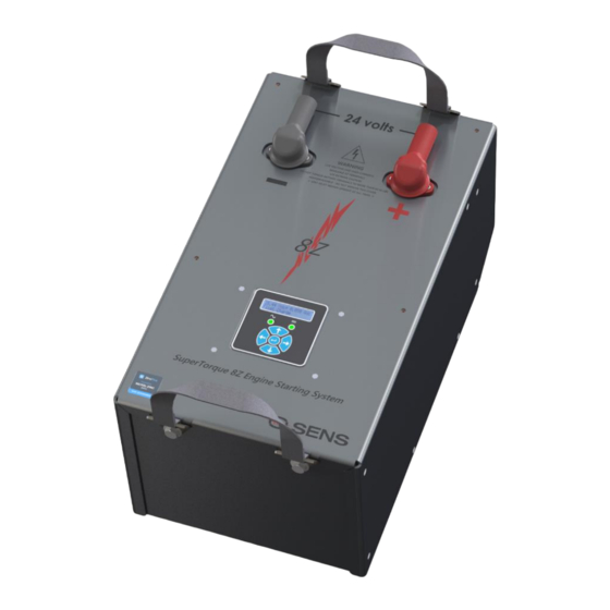
SuperTorque™ 8Z
Super High-Performance Battery + Integrated Charger System
Installation & Operation Manual
SENS Part Number:
Document Revision:
DCN Number:
Date:
PATENTED US 9,270,140; 9,385,556; 9,413,186; 9,509,164;
9,466,995
Installation or service questions?
Call SENS between 8 a.m. and 5 p.m. (Mountain Time),
Monday through Friday, or visit our website.
Copyright © Stored Energy Systems LLC 2023
The SENS name / logo and Dynamic Boost are trademarks of Stored Energy Systems LLC
Genset Starting System
101341
A
108283
April 29, 2023
SENS SuperTorque™ 8Z Technical Manual
1
1840 Industrial Circle
Longmont, CO 80501
Phone: 303.678.7500
800.742.2326
Fax:
303.678.7504
Email:
service@sens-usa.com
Web:
www.sens-usa.com
Advertisement
Table of Contents
Troubleshooting

Subscribe to Our Youtube Channel
Related Manuals for Sens SuperTorque 8Z

Summary of Contents for Sens SuperTorque 8Z
- Page 1 Call SENS between 8 a.m. and 5 p.m. (Mountain Time), Web: www.sens-usa.com Monday through Friday, or visit our website. Copyright © Stored Energy Systems LLC 2023 The SENS name / logo and Dynamic Boost are trademarks of Stored Energy Systems LLC...
-
Page 2: Table Of Contents
Restore Factory Defaults .......................... 27 9.6. Keypad Operation—Optional ........................27 9.6.3. Menu Options ............................27 9.7. Configuration and Monitoring with SENS Setup Utility ................33 9.8. Temperature Compensation ........................33 9.9. Parallel/Load Share Operation ......................... 33 9.10. Remote Alarm/Communications Panel Accessory ................... 33 SERVICE AND MAINTENANCE ........................... - Page 3 SENS SuperTorque™ 8Z Technical Manual 12.6. Charging Alarms Extended Bit Definition ....................39 12.7. Charging AC Alarms Bit Definition ......................39 12.8. Accessory Channel Alarms Bit Definition ....................39 12.9. Accessory System Alarms Bit Definition ....................40 12.10. Accessory Assigned Channel Alarms Bit Definition .................. 40 12.11.
-
Page 4: Important Safety Instructions For Installer And Operator
IMPORTANT SAFETY INSTRUCTIONS FOR INSTALLER AND OPERATOR 1.1. SAVE THESE INSTRUCTIONS – This manual contains important safety and operating instructions for SuperTorque 8Z genset starting systems. Conserver ces instructions. Ce manuel contient des instructions importantes concernant la sécurité et le fonctionnement. - Page 5 SENS SuperTorque™ 8Z Technical Manual de ces derniers. 1.9.6. Be extra cautious to reduce risk of dropping a metal tool onto the battery. It might spark or short circuit the battery or another electrical part that may cause explosion. Using insulated tools reduces this risk but will not eliminate it.
-
Page 6: Model Number Breakout
SENS SuperTorque™ 8Z Technical Manual MODEL NUMBER BREAKOUT Parameter Code Value Product Family SuperTorque 8Z 12 VDC DC Output Voltage 24 VDC Battery Capacity 80 Ah Charging Current 15 Amps Base model; includes status LEDs, two Form C relays, SENSbus, USB-C... -
Page 7: Performance Specifications
SENS SuperTorque™ 8Z Technical Manual PERFORMANCE SPECIFICATIONS SuperTorque 8Z is a genset starting system including a high-performance NiZn battery, charging system, controls, communications, and user-interface in one package, specially targeted for long-life and high reliability. 2 Standard Form C contact alarms are factory set and field reconfigurable, with indication via communication port, optional front panel LCD and assignable alarm relays. - Page 8 Optional CAN 2.0 extended ID on RJ-45 port communications Modbus Optional Modbus RS-485 or TCP/IP on RJ-45 port communications SENSbus Proprietary bus for connection of paralleled units and SENS accessories USB-C connectivity via SENS Setup Utility Environmental Operating -10°C to +55°C; storage from -20°C to +60°C temperature...
-
Page 9: System Overview
SENS SuperTorque™ 8Z Technical Manual SYSTEM OVERVIEW 4.1. Physical Overview... -
Page 10: Functional Overview
Adjustments to communications settings and other configurable settings can be made using the front panel keypad (optional) or the SENS Setup Utility software. Connect a computer with the SENS Setup Utility to the unit via USB-C. -
Page 11: Mounting Instructions
SENS SuperTorque™ 8Z Technical Manual MOUNTING INSTRUCTIONS INSTALLATION OF THE UNIT MUST COMPLY WITH LOCAL ELECTRICAL CODES AND OTHER APPLICABLE INSTALLATION CODES AND BE MADE ACCORDING TO THE INSTALLATION INSTRUCTIONS AND ALL APPLICABLE SAFETY REGULATIONS. Printed circuit boards contain static sensitive components. Damage can occur even when static levels are too low to produce a noticeable discharge shock. -
Page 12: Setup And Wiring
The unit is configured at the factory and requires no adjustments before operating. Refer to the label on the field wiring end of the unit for alarm relay assignments. Communications settings are configured using the front panel keypad (optional) or the SENS Setup Utility. 6.1. Wire Ratings All wiring must comply with applicable codes and local ordinances. -
Page 13: Dc Connection
SENS SuperTorque™ 8Z Technical Manual 6.4. DC Connection Connect DC output conductors to the DC output terminals on the unit using ring lugs and M8 fasteners. Always observe proper polarity of the DC output leads. Tighten connections to 60lb-in using a 13mm socket wrench. -
Page 14: Ac Connection
See label on the field wiring end of the unit for original factory alarm relay assignments. Alarm relay assignments are custom configurable using the SENS Setup Utility. Alarm circuits are rated 2A at 30V AC or DC. Connect alarm wiring to the respective terminals on the pluggable terminal block on the unit. To make wiring easier, the terminal block unplugs from its header. -
Page 15: Rs-485 Connection
SENS SuperTorque™ 8Z Technical Manual 2 RELAYS, 3 POSITIONS PER PULL TO REMOVE RELAY: FROM HEADER COM, OK, FAIL Position 1 Alarm Relay Connections Wire from COM to OK for alarm present on open circuit or from COM to FAIL for present on closed circuit. - Page 16 Termination may be provided as part of the network cabling or 120-ohm termination plugs for the RJ-45 communications connector on the unit are available to order separately (SENS p/n 803707). SENS units are slave devices. Pull-up and pull-down resistors are optional per Modbus specifications.
-
Page 17: Ethernet Or Sae J1939
J1939 Data High, pin 2 for J1939 Data Low and pin 3 for Common. Communications are non- isolated and referenced to negative battery terminal. An adapter from RJ45 to an 8-position terminal block may be connected to the RJ45 connector and is available to order separately (SENS p/n 208026). -
Page 18: Sensbus Connection
Use a splitter as needed in the RJ45 port on the unit to connect both the network cable and terminator. Below figure shows an example of how to terminate the network. 6.10. SENSbus Connection The unit is equipped with two SENSbus RJ45 ports. This connection is used to interconnect SENS specific devices. WARNING:... -
Page 19: Usb Connection
SENSbus RJ45 port on the unit to the remote panel splitter. Ensure a terminator remains in another SENSbus RJ45 port on the 8Z unit. 6.11. USB Connection The unit is equipped with a USB-C connector for monitoring and configuration via the SENS Setup Utility. 6.12. Verify Connections 6.12.1. -
Page 20: Start-Up Procedure
Connect alarm and communications wiring (see section 6.7). Refer to the label on the field wiring end of the unit for alarm relay assignments. Review and adjust alarm relay assignments and communications settings using the front panel keypad (optional) or the SENS Setup Utility. See section for additional... -
Page 21: Alarms, Leds And Display
SENS Setup Utility. By default, the relay contacts change state 30 seconds after the onset of a fault. The relay delay is configurable using the front panel keypad (see section 9.6) or the SENS Setup Utility. See section alarm definitions. -
Page 22: Latched Alarms
All alarm messages displayed on the front panel LCD are latching. Alarm relay configurations created using the SENS Setup Utility may be configured as latching if desired. Once an alarm condition no longer exists, the alarm message will no longer display in the main/home screen but will remain under the “Latched Alarms”... - Page 23 Over Voltage Shutdown factory alarm setpoint or the configured level if setpoint is adjusted using keypad or SENS Setup Utility. Alarm setpoint is factory configured to 16.0VDC for 12V or 32.0VDC for 24V units. The charger disables itself whenever excessive output voltage occurs while delivering current.
- Page 24 Indicates battery voltage is below the factory Startup Voltage setpoint or the configured level if setpoint is adjusted using keypad or SENS Setup Utility. When this alarm is assigned to a relay contact DC BELOW STARTUP VOLTAGE will cause the assigned relay to change to the Failed state after the time delay.
- Page 25 SENS SuperTorque™ 8Z Technical Manual 8.5.24. Battery Low Temperature Indicates battery temperature is below the Low Battery Temperature setpoint. When this alarm is assigned to a relay contact BATTERY LOW TEMPERATURE will cause the assigned relay to change to the Failed state after the time delay.
-
Page 26: Operation
Activate a Battery Check using the keypad or SENS Setup Utility. Using the keypad, navigate to the “Battery Check” menu to enable a Battery Check and configure battery check minimum voltage and duration. Upon completion of the test, the LCD will display whether the test passed or failed for ten seconds or until the “Enter”... -
Page 27: Restore Factory Defaults
9.5. Restore Factory Defaults Restore factory defaults using the front panel keypad or the SENS Setup Utility. Values that will revert to original factory settings include: Battery type... - Page 28 SENS SuperTorque™ 8Z Technical Manual Main Menus Configurable/Viewable (Press arrows to scroll (Press left/right arrows to through menu options) scroll through menus, press Parameter Descriptions up/down arrows to Main Menu Sub Menu configure values) Browse Status Scroll left/right to view basic meters and alarms...
- Page 29 SENS SuperTorque™ 8Z Technical Manual Adjust amount of time charger will be in scheduled periodic Boost mode from 1 to 255 Boost Duration hours. The Boost timer is reset if charger power is cycled Adjust amount of time between periodic Scheduled Boost scheduled Boost events from 1 to 180 days.
- Page 30 SENS SuperTorque™ 8Z Technical Manual Adjust setpoint to trigger Over Voltage Shutdown Overvolt Fault alarm, must be greater than High DC setting Adjust setpoint to trigger Low Current alarm from Low Current 0% to 50% of nominal current Adjust setpoint to trigger High Battery...
- Page 31 Adjustments of most settings are User Access Change Security Code prohibited to ensure proper operation. Contact SENS Customer Service for more information regarding setting adjustments (800-742-2326 or www.sens-usa.com). Relock Access Exit Service Mode and relock access...
- Page 32 SENS SuperTorque™ 8Z Technical Manual Minimum System Number Not applicable to 8Z units of Chargers Minimum Unit Number of Not applicable to 8Z units Chargers TCP-IP Address Set TCP-IP Address TCP-IP Gateway Set TCP-IP Gateway TCP/IP TCP-IP Subnet Mask Set TCP-IP Subnet Mask...
-
Page 33: Configuration And Monitoring With Sens Setup Utility
Communication between a computer and the unit using the SENS Setup Utility requires connection via USB-C (see section 6.11). See the SENS Setup Utility user manual for further details. -
Page 34: Service And Maintenance
Check all field wiring connections for electrical and mechanical integrity. Verify no corrosion or loose hardware is present. 10.2. Service Do not open the 8Z unit, field repair is not recommended. Contact SENS Customer Service for more information (800-742-2326 or www.sens-usa.com). 11 J1939 COMMUNICATIONS See data messages below for read-only information available using J1939. -
Page 35: Modbus Communications
Serial Modbus communications over RS-485 using RTU mode requires the optional keypad and display. Modbus communications settings may be configured using the keypad or SENS Setup Utility prior to executing communications. Configure Modbus slave address, baud rate, parity and enable/disable Modbus write access as desired. -
Page 36: Modbus Holding Registers
SENS SuperTorque™ 8Z Technical Manual 12.3. Modbus Holding Registers The 8Z unit includes an extensive array of Modbus registers. The following are common registers that are applicable to most applications. The entire list of Modbus registers is available from sens- usa.com/support/download-center/. -
Page 37: Basic Charging Alarms Bit Definition
SENS SuperTorque™ 8Z Technical Manual Unit Periodic Boost Interval between periodic boost 0x0E4 0x0E5 Countdown events (0=disabled) 0x0E6 0x0E7 Unit Line Frequency AC Line Frequency 0x0E8 0x0E9 Unit Line Voltage 1 AC Line 1 Voltage 32768 0x0EA 0x0EB Unit Line Current 1... -
Page 38: Charging Status Bit Definition
SENS SuperTorque™ 8Z Technical Manual Boost mode time limit has expired and charger has returned to Float AutoBoost 0x10 mode. Boost mode is disabled until the time limit is reset. The Boost Lockout Active time limit is reset when power is cycled. -
Page 39: Charging Alarms Extended Bit Definition
SENS SuperTorque™ 8Z Technical Manual 12.6. Charging Alarms Extended Bit Definition Bit Address Name Description Decimal Module has experienced a thermal roll back which can 0x00 Check Filter be caused by a clogged input air filter. Module has faulted because it over-heated and thermal... -
Page 40: Accessory System Alarms Bit Definition
SENS SuperTorque™ 8Z Technical Manual 12.9. Accessory System Alarms Bit Definition Bit Address Name Description Decimal Invalid System Configuration of system is conflicted. Charger will continue to operate 0x00 Config but may not be fully functional until the issue is resolved. -
Page 41: Troubleshooting/Error Codes
SENS SuperTorque™ 8Z Technical Manual 13 TROUBLESHOOTING/ERROR CODES 13.1. Configuration Error Codes Error codes are displayed on optional front panel LCD. Error Scope Description Corrective Action Charger Invalid output channel. Chargers must be - If necessary, enable the channel using the... -
Page 42: Troubleshooting
6. Incorrect address J1939 Data Low goes to pin 2. or address conflict 5. If cable wiring is correct, verify that requested command is supported by SENS unit per J1939 table in manual. 6. Check for address conflicts on the network SOLID... - Page 43 SENS SuperTorque™ 8Z Technical Manual settings (baud rate, 3. For serial applications, if cable is connected address) correctly, verify that Modbus +D1 (A) goes to connector position 1 and that Modbus –D0 (B) goes to position 2. 4. If cable wiring is correct, verify that unit and application MODBUS settings are as required.
- Page 44 SENS SuperTorque™ 8Z Technical Manual SOLID SOLID AC fail, high 1. Proper AC voltages AC LED YELLOW battery voltage or frequency not 1. Using a voltmeter, check that AC input applied voltage and frequency are in the range 2. Charger failure 80VAC –...
-
Page 45: Recycling
14 RECYCLING Contact Stored Energy Systems to recycle SuperTorque 8Z products. Stored Energy Systems will supply new SuperTorque 8Z units and the old units can be shipped to the appropriate recycling center using a provided prepaid shipping label and packaging. -
Page 46: Glossary
Equalize charging is employed to improve the performance and life of an already charged battery that is primarily charged using Float voltage. SENS’ convention is to employ the term “Boost” to mean both this cell equalization function and the fast battery recharge function. - Page 47 IN AN 8D SIZED PACKAGE USB-C • INTERNAL NICKEL ZINC BATTERIES DETAIL A 'WAKE UP' SWITCH • INTERNAL SENS MG2 15A CHARGER 'SLEEP' SWITCH SCALE 2 : 3 • USER CONNECTIONS ALL EXTERIOR, PROTECTED AND IEC 320 COVERED AC INPUT CONNECTION •...
- Page 48 Confirmation of Product Type Approval Company Name: STORED ENERGY SYSTEMS, LLC Address: 1840 INDUSTRIAL CIRCLE CO 80501 United States Product: Battery Charger Model(s): SuperTorque 8Z Endorsements: Certificate Type Certificate Number Issue Date Expiry Date Product Design Assessment (PDA) 22-2316015-PDA 09-JAN-2023...
- Page 49 Certificate Number: 22-2316015-PDA Unit Certification is not required for this product (ratings less than 25 kW). If the manufacturer or purchaser requests an ABS Certificate for compliance with a specification or standard, the specification or standard, including inspection standards and tolerances, must be clearly defined.
- Page 50 Certificate Number: 22-2316015-PDA International Standards EU-MED Standards National Standards UL 9540A, November 12, 2019 Government Standards Other Standards Corporate ABS Programs American Bureau of Shipping Print Date and Time: 10-Jan-2023 11:42 ABS has used due diligence in the preparation of this certificate, and it represents the information on the product in the ABS Records as of the date and time the certificate is printed.
- Page 51 Stored Energy Systems Manufacture Address: 1840 Industrial Circle Longmont, CO 80501 U.S.A. Product Type: SuperTorque 8Z Engine Starting System Model Numbers: 8Z-XX-X-XX-X-X-X-XX, where X = any digit; Conformance to Directive 2014/30/EU of the European Parliament and of the Council Directives:...
- Page 52 Manufacturer: Stored Energy Systems Manufacture Address: 1840 Industrial Circle Longmont, CO 80501 U.S.A. Product Type: SuperTorque 8Z Engine Starting System Model Numbers: 8Z-XX-X-XX-X-X-X-XX, where X = any digit; Conformance to Electromagnetic Compatibility Regulations 2016 Directives: Electrical Equipment (Safety) Regulations 2016...
- Page 53 Contact SENS service department to obtain warranty service instructions. To obtain warranty service the system must be returned, freight prepaid, to the service facility specified by SENS under a Return Material Authorization (RMA) number provided by SENS. If, in SENS’ opinion, the problem can be rectified in the field, SENS may elect to ship replacement parts for customer installation instead or in advance of returning the system component to the service facility.
Need help?
Do you have a question about the SuperTorque 8Z and is the answer not in the manual?
Questions and answers