
Related Manuals for Purified Air UV-O 500


Summary of Contents for Purified Air UV-O 500
- Page 1 UV-O Odour Control Units Technical and Operations Manual Models Covered: UV-O 500 UV-O 1000...
-
Page 3: Using This Manual
UV-O Odour Control Units Using this Manual This manual is intended to be used as a work of reference by professional, well trained and authorised users to assist them in safely installing, using, maintaining and repairing the Units mentioned on the cover of this document. Please note that it is strongly recommended that training is given by Puried Air Limited prior to operatives attempting to carry out maintenance or repair work on these Units. -
Page 4: Copyright Statement
UV-O Odour Control Units Copyright Statement All rights reserved No part of this publication may be copied or published by means of printing, photocopying, microlm or otherwise without prior written consent o the manuacturer. This restriction also applies to the corresponding drawings and diagrams. The information given in this manual has been collected for the general convenience of our clients. - Page 6 UV-O Odour Control Units Safety Introduction Everyone working on or with these Units must be familiar with the contents of this manual and must strictly observe the instructions herein. The Management should instruct personnel in accordance with this manual and observe all instructions and directions given herein.
-
Page 7: Safety Warnings And Instructions
UV-O Odour Control Units Safety Warnings and Instructions The ollowing symbols and notications are used in this manual: WARNING! Used to indicate where there is a risk of injury or death. WARNING! - DANGER OF ELECTRIC SHOCK! Used to indicate where there is a risk of injury or death from electric shock. -
Page 8: Pictograms, Warnings And Instructions Displayed On The Unit
& eyes, isolate before opening. WARNING This system produces ozone. If you smell ozone isolate unit and ventilate area. Figure 1 - UV-O 500 Unit Label UV-O 1000 0800 0184000 www.purifiedair.com WARNING This system contains UV light which is harmful to skin &... -
Page 9: Safety Warnings And Cautions
UV-O Odour Control Units CAUTION ● All saety eatures must be correctly tted and can only be removed for maintenance and repair jobs by skilled and authorised service engineers. ● These Units must not be used if the safety features are not fully present or defective. - Page 10 UV-O Odour Control Units CAUTION ● Regularly inspect your Unit and check it for damage. ● Verify the correct functioning of all of the safety features. ● Read and save all notices, warnings and safety instructions received with your Unit. ●...
-
Page 11: Technical Specifications
Rating Plates odl UVO V r o UVO Figure 3 - UV-O 500 Unit Rating Plate odl UVO V r o Figure 4 - UV-O 1000 Unit Rating Plate... -
Page 12: Product Overview
UV-O Odour Control Units Product Overview Figure 5 - UV-O 500 Unit Figure 6 - UV-O 1000 Unit Installed Intended Use UV-O Odour Control Units are designed to eiciently remove odorous compounds rom the fumes extracted from commercial kitchens. Simple to install, the Units are designed to be located on the outside of the ducting. The fact that they are externally located makes these Units ideal for retrospective installations and, as the UV lamps are outside of the airstream, maintenance requirements are minimal. -
Page 13: Operating Principles
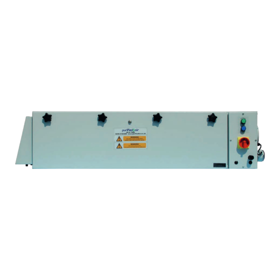
Unit. Operating Principles Puried Air’s UV-O Odour Control Units contain either two (UV-O 500) or ten (UV-O 1000) high output UV-C (short-wavelength ultraviolet radiation) lamps and are designed to be located outside the extraction duct. - Page 14 2.4.1 UV-O 500 Components The UV-O 500 Unit consists of a Main Chassis which contains the UV lighting source behind a lockable, hinged, access panel. A green Power Light and blue Saety Light are located on the lower Panel o the Unit.
- Page 15 View On ‘A’ Front View View On ‘B’ Air Flow Sensor Figure 7 - UV-O 500 - Views Figure 8 - Air Flow Sensor Figure 9 - Air Inlet 2.4.2 UV-O 1000 Components The UV-O 1000 Unit consists of a Main Chassis which contains the UV lighting source behind a lockable hinged access panel also secured with our star knobs.
- Page 16 UV-O Odour Control Units 11) is mounted on the right hand side o the Main Chassis below the Airow Outlet/Duct Connection Spigot. The Air Inlet, containing the Unit’s lter, is located on the let hand side o the Unit (See Figure 12 - Air Inlet on page 12).
- Page 17 UV-O Odour Control Units Figure 12 - Air Inlet Technical and Operations Manual - Product Overview...
Need help?
Do you have a question about the UV-O 500 and is the answer not in the manual?
Questions and answers