Purified Air UV-O 1000 Technical & Operating Instructions
Hide thumbs
Also See for UV-O 1000:
- Technical and operations manual (58 pages) ,
- Technical and operations manual (18 pages)
Advertisement
Quick Links
Advertisement

Related Manuals for Purified Air UV-O 1000


Summary of Contents for Purified Air UV-O 1000
- Page 1 UV-O 1000 TECHNICAL & OPERATION MANUAL...
- Page 2 This product contains lamps that produce UV light. Immediate or prolonged exposure to UV light can result in painful eye injury, skin burn, premature skin aging, or skin cancer. This product creates OZONE (O ). Inhalation of ozone causes dryness of the mouth, coughing, and irritates the nose, throat, and chest.
-
Page 3: Safety Instructions And Warnings
Please note that it is strongly recommended that training is given by Purified Air Ltd prior to operatives attempting to carry out maintenance or repair work on this product. - Page 4 Intended use The product has been designed exclusively for the treating odours which are released during the most common cooking processes in commercial kitchens. Using the product for other purposes The manufacturer accepts no liability for any is considered contrary to its intended use. damage or injury resulting from such use.
- Page 5 UV lamps can be viewed or come into contact with skin. If ozone can be smelt in the area where the UV-O 1000 unit is installed, it has been incorrectly installed and should be isolated. Contact Purified Air for further information.
-
Page 6: General Description
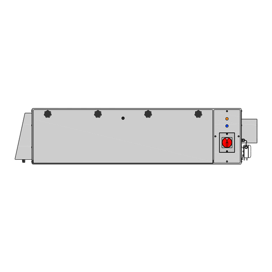
GENERAL DESCRIPTION This UV-O 1000 can remove, at high efficiency, odorous compounds. The UV-O 1000 is designed to be installed in the extraction ducting of a commercial kitchen down stream of the extraction hood and upstream of the fan. POWER LIGHT (ORANGE) -
Page 7: Installation
Fix the negative pressure probe only (using a 2mm drill and 7mm drill) to the BRANCH DUCT which connects the UV-O 1000 to the main extract duct, connecting this via the PVC tube to port P1 and leave unused port P2 open to atmosphere (see Fig.3 & Fig.4). Also link the power supply between the extract fan and the UV-O 1000. - Page 8 150mm diameter galvanised metal ducting should be used to connect the UV-O 1000 unit to the kitchen extract duct (see Fig.2). The ducting should connect securely to the spigot on the front of the unit and should spigot into the kitchen extract duct.
- Page 9 Once the UV-O 1000 has been mounted and the ducting connected the special UV lamps should be inserted. Access is via the front panel which hinges open once the lock and star knobs have been released. The lamp holder can be pulled clear of the unit on a runner system to make installation of the lamps easier.
- Page 10 The UV-O 1000 should now be wired into the mains via the isolator on the front of the unit. Wiring diagram Fig.7 Once unit is wired and necessary safety requirements have been adhered to the UVO-1000 can be switched on. The safety switch light indicates that the various safety switches, the airflow and micro switch are engaged and that airflow is present.
-
Page 11: Maintenance
The maintenance of the UVO-1000 unit is a very specialist task and should not be carried out by anyone who has not received specialist training by Purified Air Limited If you carry out the simple maintenance and cleaning described below at the regular intervals, then any problems will mostly be detected and corrected before they result in a total breakdown of the product. - Page 13 Purified Air Ltd, Lyon House, Lyon Road, Romford, Essex. RM1 2BG ENGLAND Tel: 01708 755414 Fax: 01708 721488 e-mail: enq@purifiedair.com website: www.purifiedair.com...
Need help?
Do you have a question about the UV-O 1000 and is the answer not in the manual?
Questions and answers