
Related Manuals for Purified Air UV-O 500


Summary of Contents for Purified Air UV-O 500
- Page 1 UV-O Odour Control Units Technical and Operations Manual Models Covered: UV-O 500 UV-O 1000...
- Page 3 Units mentioned on the cover of this document. Please note that it is strongly recommended that training is given by Purified Air Limited prior to operatives attempting to carry out maintenance or repair work on these Units.
- Page 4 UV-O Odour Control Units Copyright Statement All rights reserved No part of this publication may be copied or published by means of printing, photocopying, microfilm or otherwise without prior written consent of the manufacturer. This restriction also applies to the corresponding drawings and diagrams. The information given in this manual has been collected for the general convenience of our clients.
-
Page 5: Table Of Contents
4.4 Installing the UV-O 1000 Unit 5. Operation and Control 5.1 UV-O 500 Control Panel 5.2 UV-O 1000 Control Panel 5.3 Before Use 5.4 Switching the UV-O 500 Unit On 5.5 Switching the UV-O 1000 Unit On 5.6 BMS Connections 6. Maintenance 6.1 Introduction 6.2 Cleaning and Maintenance Tasks -... -
Page 7: Safety
UV-O Odour Control Units Safety Introduction Everyone working on or with these Units must be familiar with the contents of this manual and must strictly observe the instructions herein. The Management should instruct personnel in accordance with this manual and observe all instructions and directions given herein. -
Page 8: Safety Warnings And Instructions
UV-O Odour Control Units Safety Warnings and Instructions The following symbols and notifications are used in this manual: WARNING! Used to indicate where there is a risk of injury or death. WARNING! - DANGER OF ELECTRIC SHOCK! Used to indicate where there is a risk of injury or death from electric shock. -
Page 9: Pictograms, Warnings And Instructions Displayed On The Unit
& eyes, isolate before opening. WARNING This system produces ozone. If you smell ozone isolate unit and ventilate area. Figure 1 - UV-O 500 Unit Label UV-O 1000 0800 0184000 www.purifiedair.com WARNING This system contains UV light which is harmful to skin &... -
Page 10: Safety Warnings And Cautions
UV-O Odour Control Units CAUTION ● All safety features must be correctly fitted and can only be removed for maintenance and repair jobs by skilled and authorised service engineers. ● These Units must not be used if the safety features are not fully present or defective. ● The safety features should be regularly checked for their proper functioning and, if defective, should be immediately repaired. -
Page 11: Modifications
UV-O Odour Control Units CAUTION ● Regularly inspect your Unit and check it for damage. ● Verify the correct functioning of all of the safety features. ● Read and save all notices, warnings and safety instructions received with your Unit. ●... -
Page 12: Technical Specifications
Rating Plates Model: UVO 500 230V/1 ~ /50Hz Ser. No.: UVO52017 01001 140W Figure 3 - UV-O 500 Unit Rating Plate Model: UVO 1000 230V/1 ~ /50Hz Ser. No.: E10121 4 001001 700W Figure 4 - UV-O 1000 Unit Rating Plate... -
Page 13: Product Overview
UV-O Odour Control Units Product Overview Figure 5 - UV-O 500 Unit Figure 6 - UV-O 1000 Unit Installed Intended Use UV-O Odour Control Units are designed to efficiently remove odorous compounds from the fumes extracted from commercial kitchens. Simple to install, the Units are designed to be located on the outside of the ducting. The fact that they are externally located makes these Units ideal for retrospective installations and, as the UV lamps are outside of the airstream, maintenance requirements are minimal. -
Page 14: Features
Unit. Operating Principles Purified Air’s UV-O Odour Control Units contain either two (UV-O 500) or ten (UV-O 1000) high output UV-C (short-wavelength ultraviolet radiation) lamps and are designed to be located outside the extraction duct. -
Page 15: Components
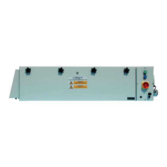
2.4.1 UV-O 500 Components The UV-O 500 Unit consists of a Main Chassis which contains the UV lighting source behind a lockable, hinged, access panel. A green Power Light and blue Safety Light are located on the lower Panel of the Unit. - Page 16 View On ‘A’ Front View View On ‘B’ Air Flow Sensor Figure 7 - UV-O 500 - Views Figure 8 - Air Flow Sensor Figure 9 - Air Inlet 2.4.2 UV-O 1000 Components The UV-O 1000 Unit consists of a Main Chassis which contains the UV lighting source behind a lockable hinged access panel also secured with four star knobs.
- Page 17 UV-O Odour Control Units 11) is mounted on the right hand side of the Main Chassis below the Airflow Outlet/Duct Connection Spigot. The Air Inlet, containing the Unit’s filter, is located on the left hand side of the Unit (See Figure 12 - Air Inlet on page 12).
- Page 18 UV-O Odour Control Units Figure 12 - Air Inlet Technical and Operations Manual - Product Overview...
-
Page 19: Storage, Unpacking And Handling
● This Technical and Operations Manual. It is strongly recommended that Purified Air commission the UV-O Unit. However, should the customer decide to complete these tasks (See 4.3.3 Commissioning the UV-O 500 Unit on page 20 and 4.4.3 Commissioning the UV-O 1000 Unit on page 27) -
Page 20: Installation Guidance
It is strongly recommended that UV-O Units are commissioned by Purified Air Ltd to ensure that they are installed correctly and safely. If in any doubt regarding the installation of the UV-O Units, contact Purified Air Ltd. Unit Dimensions The dimensions of the UV-O Units are detailed below. -
Page 21: Installing The Uv-O 500 Unit
Branch Duct Figure 15 - UV-O 500 Installation Schematic Before installation, the following points should be considered: ● The UV-O 500 Unit should be located in close proximity to the kitchen extract ducting. Technical and Operations Manual - Installation Guidance... - Page 22 UV-O 500 Mounting Holes Rigid 100mm diameter galvanised metal ducting should be used to connect the UV-O 500 Unit to the kitchen extraction ducting (See Figure 15 - UV-O 500 Installation Schematic on page 15). The 100mm galvanised metal ducting should connect securely to the spigot on the side of the Unit and be connected to the kitchen extraction ducting via a spigot.
- Page 23 To this end, an Air Flow Sensor and Pressure Probe, measuring air pressure in the extraction ducting, are fitted to the UV-O 500 and only allow the Unit to operate when a sufficient volume of air is flowing through the extraction ducting.
- Page 24 Solid Spiral Branch Duct Pressure Probe P2 Open to Atmosphere PVC Tubing fixed to P1 Figure 19 - Connecting the Air Flow Sensor’s Pressure Probe Link the extraction fan and UV-O 500 power supplies. Technical and Operations Manual - Installation Guidance...
- Page 25 UV-O Odour Control Units Turn on the extraction fan and confirm that air is passing through the Unit’s air inlet and passing into the extraction ducting. WARNING Under no circumstances should the Unit be used if the direction of the airflow is reversed and air is exiting from the Unit’s air inlet.
- Page 26 On receipt of the signed UVC Disclaimer, Purified Air will supply the correct number and type of lamps required for the UV-O unit ordered along with a set of keys.
- Page 27 UV-O Odour Control Units Wire the UV-O 500 Unit into the mains via an isolating switch (not supplied) mounted not more than 1 meter from the Unit, in an easily accessible location: Isolation Switch (Not Supplied) Mains Power In Rotary Mains...
- Page 28 UV-O Odour Control Units Figure 23 - Electrical Connections Technical and Operations Manual - Installation Guidance...
-
Page 29: Installing The Uv-O 1000 Unit
To check that all UV lamps are working it is necessary to bypass the micro- switches on the inside top front of the UV-O 500 to enable the Front Panel to be open when the Unit is in operation. This procedure should only be undertaken by a qualified Purified Air engineer. - Page 30 UV-O Odour Control Units ● Alternatively, mounting brackets are supplied that can be fixed to the spigot and inlet plates via the bolts already in place, as shown below: Figure 2 5 - UV-O 1 000 Mounting Bracket Installation Rigid 100mm diameter galvanised metal Branch Duct should be used to connect the UV- O 1000 Unit to the kitchen extraction ducting (See Figure 24 - UV-O 1000 Main Chassis Installation Schematic on page 23).
- Page 31 UV-O Odour Control Units 4.4.2 Installing the UV-O 1000 Pressure Probe The UV-O 1000 must only be allowed to operate when the kitchen’s fume extraction system is running. To this end, an Air Flow Sensor and Pressure Probe, measuring air pressure in the extraction ducting, are fitted to the UV-O 1000 and only allow the Unit to operate when a sufficient volume of air is flowing through the extraction ducting: The Air Flow Sensor will switch on power to the Unit if the air pressure in the duct is...
- Page 32 UV-O Odour Control Units Solid Spiral Branch Duct Pressure Probe Self Tapping Screw Port P1 Port P2 Air Flow Tubing Sensor Figure 2 7 - Installing the Air Flow Sensor’s Pressure Probe Connect the Pressure Probe via the PVC tube to Port P1 on the Air Flow Sensor, leaving Port P2 unused and open to the atmosphere (see Figure 27 above).
- Page 33 On receipt of the signed UVC Disclaimer, Purified Air will supply the correct number and type of lamps required for the UV-O unit ordered along with a set of keys.
- Page 34 UV-O Odour Control Units Figure 29 - Lamp Clips Figure 30 - Lamp Plugs F igure 31 - UV-O 1000 UV Lamp Technical and Operations Manual - Installation Guidance...
- Page 35 The ability to connect a Building Management System (BMS) to the UVO range of units is an optional extra. If required this can be ordered with the unit and fitted by Purified Air before dispatch at an additional cost, alternaitvely it can be retro fitted once installed on site, again by an experienced Purified Air engineer, but this does incur a higher additional cost.
-
Page 36: Operation And Control
The lower, angled section of the front of the Unit’s main case contains a green Power Light and blue Safety Switch Light. Figure 32 - UV-O 500 Control Panel UV-O 1000 Control Panel A Control Panel is situated on the right hand side of the Main Chassis which contains the Rotary Mains Isolation Switch, Green Power Light and Blue Safety Switch Light. -
Page 37: Before Use
Safety Switch Light don’t illuminate when the Rotary Mains Isolation Switch is in the ‘On’ position. WARNING ● If ozone can be smelt in the area where the UV-O 500 Unit is installed, the Unit has been incorrectly installed ● It should be isolated via the Mains Isolator Switch and Purified Air contacted for further information. -
Page 38: Switching The Uv-O 1000 Unit On
Any BMS connection to this unit should be 24V 0.5A max. The BMS relay has volt free contacts. When the unit is isolated the BMS connection could still be LIVE. If you have any queries regarding this please contact Purified Air Limited. Technical and Operations Manual - Operation and Control... -
Page 39: Maintenance
● Do not carry out any service, maintenance or repairs on the Unit before it has been protected against unintended starting. 6.1.1 Maintenance Schedule UV-O 500 and UV-O 1000 Basic maintenance activities can be carried out by the user. Please see the table below for the optimum frequencies for such activities. -
Page 40: Cleaning And Maintenance Tasks - Uv-O 500
Cleaning and Maintenance Tasks - UV-O 500 It is a matter of experience to determine when your UV-O 500 Unit needs to be cleaned as the nature and degree of any pollution depends strongly on factors such as the particular location, humidity and the intensity of use etc. - Page 41 Slide the lamps to the right to disengage them from their plugs (See Figure 34 - UV-O 500 UV Lamp Plugs below). Remove the lamps from their clips (See Figure 35 - UV-O 500 Lamp Clips on page 36). Clean the lamps by wiping them with alcohol wipes or a lint free cloth soaked in isopropyl alcohol and dry with a lint free cloth.
- Page 42 Having disconnected the mains power supply to the Unit, opened its Front Panel and removed the UV Lamps (See 6.2.1 Cleaning the UV-O 500 lamps on page 34): Spray a suitable cloth or paper towel with a high quality degreaser and wipe over the Unit’s internal surfaces.
-
Page 43: Cleaning And Maintenance Tasks - Uv-O 1000
UV-O Odour Control Units Cleaning and Maintenance Tasks - UV-O 1000 It is a matter of experience to determine when your UV-O 1000 Unit needs to be cleaned as the nature and degree of any pollution depends strongly on factors such as the particular location, humidity and the intensity of use etc. - Page 44 UV-O Odour Control Units Switch to the ‘On’ position. 6.3.3 Replacing the UV-O 1000 Filter Isolate the Unit from the mains power supply by turning the Rotary Mains Isolator Switch to the ‘Off’ position. Double check that the mains power supply has been isolated. Undo the lock, unscrew the four Star Knobs anti-clockwise on the Front Panel and open it.
- Page 45 UV-O Odour Control Units 6.3.4 Cleaning the Inside of the UV-O 1000 Isolate the Unit from the mains power supply by turning the Rotary Mains Isolator Switch to the ‘Off’ position. Double check that the mains power supply has been isolated. Undo the lock, unscrew the four Star Knobs anti-clockwise on the Front Panel and open it.
-
Page 46: Troubleshooting
UV-O Odour Control Units Troubleshooting If your UV-O Unit does not function correctly, consult the checklist below to see if you can correct the error yourself. INFORMATION A number of problems in the checklist below can also be caused by defects in equipment connected to the Unit. -
Page 47: Commissioning Waiver
The customer owns the Unit and is entitled to have keys to it. However, before releasing keys to the customer Purified Air require a Director of the company to sign a Commissioning Waiver acknowledging that it is fully understood about the dangers associated with this Unit and will take every precaution to ensure that no person comes to harm when accessing the Unit. -
Page 48: Wiring Diagrams
UV-O Odour Control Units Wiring Diagrams UV-O 500 UVO-500 WIRING DIAGRAM DOOR MICRO SWITCH MAINS ELECTRIC POWER ON AIR FLOW LAMP (GREEN) IN 230V AC SWITCH 2A FUSE ANTI SURGE PE STUD SAFETY LAMP (BLUE) BALLAST UV LAMPS Figure 3 7 -... -
Page 49: Uvo 500 Bms
UV-O Odour Control Units UVO 500 BMS UVO-500 WIRING DIAGRAM WITH BMS CONNECTION DOOR MICRO SWITCH MAINS ELECTRIC POWER ON AIR FLOW IN 230V AC LAMP (GREEN) SWITCH 2A FUSE ANTI SURGE PE STUD SAFETY LAMP (BLUE) BALLAST UVO-500 BMS CONNECTION BMS VOLT FREE CONTACT. -
Page 50: Uv-O 1000
UV-O Odour Control Units UV-O 1000 Figure 39 - UV-O 1000 Unit Wiring Diagram Technical and Operations Manual - Wiring Diagrams... -
Page 51: Uv-O 1000 Bms
UV-O Odour Control Units UV-O 1000 BMS Figure 40 - UV-O 1000 BMS Unit Wiring Diagram Technical and Operations Manual - Wiring Diagrams... -
Page 52: Equipment Disposal
UV-O Odour Control Units 10. Equipment Disposal 10.1 Packaging Material Disposal INFORMATION The Unit’s packaging materials are manufactured from recyclable materials in accordance with applicable local regulations. The purpose of the packaging is to protect the Unit during transport. It consists of the following substances that can be reused: ●... -
Page 53: Dependability
UV-O Odour Control Units 11. Contact Details At Purified Air, we pride ourselves on our excellent levels of customer service and maintenance. 11.1 Nationwide Coverage We have hubs in both Manchester and London and can offer nationwide coverage with teams of directly employed service engineers. -
Page 54: 12. Warranty Statement
● The cost of functional replacement parts, but excluding consumable items. ● The labour costs of a Purified Air approved repairer to carry out the repair. What is not covered? ● Transit, delivery or accidental damage or misuse and abuse. -
Page 55: Certification
Email: enq@purifiedair.co.uk www.purifiedair.co.uk EC Declaration of Conformity Document Number: DoC UVC 1201 We; Purified Air Limited at above address, declare the products detailed below comply with the requirements of the following EU Directives, Low Voltage Directive 20 / 5/EU Electromagnetic Compatibility Directive 2004/108/EC... - Page 56 UV-O Odour Control Units Technical and Operations Manual -...
- Page 57 UV-O Odour Control Units Technical and Operations Manual -...
- Page 58 FreePhone (UK Only) 0800 018 4000 International +44 1708 755414 Purified Air Limited. Lyon House, Lyon Road, Romford, Essex. RM1 2BG www.purifiedair.com ¦ enq@purifiedair.com Edition 1...
Need help?
Do you have a question about the UV-O 500 and is the answer not in the manual?
Questions and answers