Table of Contents
Advertisement
Quick Links
I I n n t t r r o o d d u u c c t t i i o o n n
D D e e s s c c r r i i p p t t i i o o n n
TEC-N2 Series Thermostat
Note: In this document, Building Automation System (BAS) is a generic
term that refers to the Metasys® Network (Network Control
Module [NCM] or N30 series), Companion™, and Facilitator™
supervisory systems. The specific system names are used when
referring to system specific applications.
The TEC-N2 series includes two nonprogrammable models: multi stage
heat pump (HP32-N2) and multi stage gas/electric (GE22-N2). The appli-
cations include furnace, air conditioner, heat pump, and rooftop units.
The TEC-N2 incorporates fuzzy logic for precise control in a thermostat
type package.
All TEC-N2s have Metasys N2 communication capability. This communi-
cation allows the user to view and adjust parameters from a remote work-
station. It also provides information, such as outside air temperature, to the
TEC-N2 units on the bus. The thermostat is easy to operate and normally
displays room temperature and mode of operation using cooling (j) or
heating (i) icons. When there is a call for cooling, the snowflake icon (j)
blinks. Likewise, on a call for heating, the flame icon (i) blinks. When the
temperature is satisfied, neither will blink. In the auto mode, both icons
(ji) display continuously when satisfied. Light-emitting diodes (LEDs)
on the top of both models use binary inputs (BIs) to indicate a clogged fil-
ter and external service. A unique temperature alarm (BI 2) indicates that
the zone temperature has not been satisfied in 45 minutes.
Used to select heating, cooling,
auto, off, or emergency heat
Mode
(E ht; available on HP32-N2
only) mode of operation.
Used to run fan
continuously.
LEDs indicate system activity
or problems (see Table 3).
75
Outdoor
Fan
Day/Night
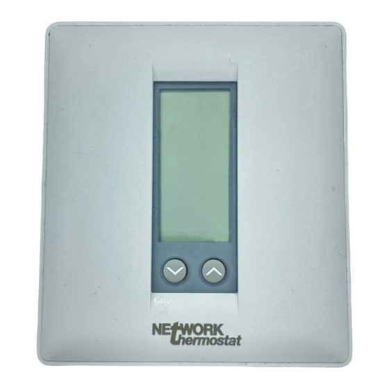
Figure 1: TEC-N2
Used to display outside
temperature (optional).
Used to alternate between
day and night setpoints.
Time occuppied mode when
keyboard locked.
Used to increase/decrease values
or change between °C or °F.
www.networkthermostats.com
1
Advertisement
Table of Contents

Related Manuals for Network Thermostat TEC-N2 Series


Summary of Contents for Network Thermostat TEC-N2 Series
- Page 1 D D e e s s c c r r i i p p t t i i o o n n The TEC-N2 series includes two nonprogrammable models: multi stage heat pump (HP32-N2) and multi stage gas/electric (GE22-N2). The appli- cations include furnace, air conditioner, heat pump, and rooftop units.
- Page 2 (2) This device must accept any interference received, including interference that may cause undesired operation. This Class A digital apparatus meets all of the requirements of the Canadian Interference-Causing Equipment Regulations. Cet appareil numerique de la classe A respecte toutes les exigences du Reglement sur le materiel brouilleur du Canada. TEC-N2 Series Thermostat...
- Page 3 Table 2: TEC-N2 Series Accessory Ordering Information Item Product Code Number Optional Accessories (includes mounting hardware) Remote or Averaging Indoor Temperature Sensor with Communication Module NT-IDS Outdoor Air Sensor with Outdoor Air Temperature Communication Module NT-ODT Duct Mounted Supply Air Sensor with Outdoor Air Temperature...
-
Page 4: Required Installation Tools
Note: Two plastic anchors with screws and the cover lock are included with the TEC-N2s. Note: Mount the TEC-N2 series thermostat on an interior wall, approxi- mately 1.5 m (5 ft) above the floor in a location of average tem- perature (e.g., 72°F). -
Page 5: Setting The Dip Switches
Switches or cooling. Note: Before selecting a minimum on/off time for the TEC-N2 series, verify the equipment can tolerate the following hourly maximum cycle rates: 7.5 cycles per hour when using 4-minute on/off (pre- ferred for energy savings) or 15 cycles per hour when using 2-minute on/off. - Page 6 LED2 icon Off LED2 icon 1st Stage Compressor (Wrench/Fault) CLK1 CLK2 24VAC Power In 24VAC Common 24V(C) RS+V Cool Reversing Valve Heat Reversing Valve N2 REF Figure 3: HP32-N2 Heat Pump, Factory-Set DIP Switch Settings, and Wiring Configuration TEC-N2 Series Thermostat...
- Page 7 24V(c) Equipment LED2 CLK2 RS+V Reverse First Stage Valve Compressor Heating Second Reverse Remote Remote Auxiliary Stage Valve Sensor Clock/Timer Heat Compressor Cooling (if used) (if used) Field Contact Switches Figure 4: HP32-N2 Heat Pump Wiring Schematic TEC-N2 Series Thermostat...
- Page 8 GE22-N2 (Wrench/Fault) LED1 2nd Stage Cooling 1st Stage Heating LED2 1st Stage Cooling CLK1 CLK2 24VAC Power In Common 24V(c) RS+V 2nd Stage Heating N2 REF Figure 5: GE22-N2 Multistage Factory-Set DIP Switch Setting and Wiring Configuration TEC-N2 Series Thermostat...
-
Page 9: Connecting The N2 Bus
Note: Each TEC-N2 has self-terminating End-of-Line (EOL) resistors. However, one EOL is needed at the BAS (two are preferred at opposite ends). 2. Continue this process for each TEC-N2 using the daisy chain wiring method (Figure 7). TEC-N2 Series Thermostat... - Page 10 N2 REF Device Figure 8: Connecting the TEC-N2 to the N30 Series Connecting to the Companion/ Facilitator System TEC-N2 Companion/Facilitator Transformer 24VAC 24VAC N2 Bus Connector N2 REF Figure 9: Connecting the TEC-N2 to the Companion/Facilitator System TEC-N2 Series Thermostat...
- Page 11 Control System (CS) object only. Note: For the TEC-N2, do not use the Adjust command with the Companion/Facilitator (CPN/FAC) system, since it is not support- ed. The TEC-N2 responds with an offline message but continues to operate normally. TEC-N2 Series Thermostat...
- Page 12 0 = Normal, 1 = Alarm ♦ ♦ Temp Alarm BI-2 N2 BI (BI) CSBI BI2 0 = Normal, 1 = Alarm ♦ ♦ Filter BI-3 N2 BI (BI) CSBI BI3 0 = Normal, 1 = Alarm Notes: See following page. TEC-N2 Series Thermostat...
-
Page 13: Installing The Thermostat Cover Lock
1. Position the thermostat inside the cover, and attach on the hinged tabs located at the top of the base. 2. Swing the thermostat and cover down. 3. Press on the bottom center edge until plastic lock snaps in place (Figure 11). TEC-N2 Series Thermostat... - Page 14 22-30 VDC. Binary input 2 is the temperature alarm binary data point that will cause a COS if the zone temperature is moving away from the setpoint after 45 minutes. The COSs N2 Address Push FAN and MODE buttons simultaneously and hold for ten seconds to view address. TEC-N2 Series Thermostat...
-
Page 15: Selecting An Operation Mode
74°F). When the heat icon is off, adjust the setpoint 2°F higher (76°F), to energize the auxiliary heat (HP32-N2 model only). Press the MODE button to select from the modes listed in Table 11. Selecting an Operation Mode Table 11: TEC-N2 Series Thermostat Modes Mode Description COOL When the snowflake icon ( ) and the word COOL are displayed, the thermostat is in the cooling mode. - Page 16 3. Press the OUTDOOR button. LobP appears in the display, meaning low balance point, along with the current balance setpoint. 4. Press the ∨ ∨ and ∧ ∧ buttons to set the low balance point temperature. 5. Press the MODE button to resume operation. TEC-N2 Series Thermostat...
-
Page 17: Sensor Calibration
Selecting Day or When the TEC-N2 series thermostat is first installed, or after a power Night Mode (ef) loss, the display shows the day icon (e) and the temperature. Once the BAS overrides the day or night mode, the corresponding symbol will be displayed. - Page 18 MM-CVT101 is not plugged into PC or Plug MM-CVT101 into PC or plug it into a 120 VAC source. 120 VAC source. Wiring near the BAS is broken. Repair the wiring. No point mapping entered. Define the BAS database. TEC-N2 Series Thermostat...
- Page 19 C C o o m m p p l l a a i i n n t t s s temperature control problems with TEC-N2 series thermostats. T T r r o o u u b b l l e e s s h h o o o o t t i i n n g g...
- Page 20 NetworkThermostats.com 352-00150-001 Rev A...
Need help?
Do you have a question about the TEC-N2 Series and is the answer not in the manual?
Questions and answers