Table of Contents
Advertisement
SPLIT-TYPE, HEAT PUMP AIR CONDITIONERS
SERVICE MANUAL
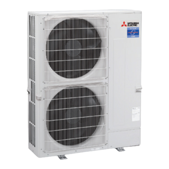
Outdoor unit
[Model Name]
PUHZ-ZRP200YKA3
PUHZ-ZRP250YKA3
[Service Ref.]
PUHZ-ZRP200YKA3.UK
PUHZ-ZRP250YKA3.UK
R410A
CONTENTS
1. REFERENCE MANUAL ································· 2
2. SAFETY PRECAUTION ································· 2
3. FEATURES ····················································· 6
4. SPECIFICATIONS ·········································· 7
5. DATA ······························································· 8
6. OUTLINES AND DIMENSIONS ··················· 11
7. WIRING DIAGRAM ······································ 12
8. WIRING SPECIFICATIONS ·························· 13
9. REFRIGERANT SYSTEM DIAGRAM ············· 18
10. TROUBLESHOOTING ······························· 20
11. FUNCTION SETTING ································· 75
13. EASY MAINTENANCE FUNCTION ··········· 93
14. DISASSEMBLY PROCEDURE ·················· 96
PARTS CATALOG (OCB680)
November 2017
No. OCH680
Note:
• This manual describes service
data of the outdoor units only.
Advertisement
Table of Contents

Related Manuals for Mitsubishi Electric PU-ZRP200YKA3


Summary of Contents for Mitsubishi Electric PU-ZRP200YKA3
-
Page 1: Table Of Contents
SPLIT-TYPE, HEAT PUMP AIR CONDITIONERS November 2017 No. OCH680 SERVICE MANUAL R410A Outdoor unit [Model Name] [Service Ref.] PUHZ-ZRP200YKA3.UK PUHZ-ZRP200YKA3 Note: • This manual describes service data of the outdoor units only. PUHZ-ZRP250YKA3.UK PUHZ-ZRP250YKA3 CONTENTS 1. REFERENCE MANUAL ································· 2 2. -
Page 2: Reference Manual
REFERENCE MANUAL INDOOR UNIT SERVICE MANUAL Service Model Name Service Ref. Manual No. OCH650 PLA-ZM50/60/71/100/125EA PLA-ZM50/60/71/100/125EA.UK OCB650 OCH626 PLA-RP50/60/71/100/125EA PLA-RP50/60/71/100/125EA.UK OCB626 OCH492 PCA-RP71HAQ PCA-RP71HAQ(-ER) OCB492 OCH659 PCA-M50/60/71/100/125KA PCA-M50/60/71/100/125/KA OCB659 OCH660 PKA-M50HA(L) PKA-M50HA(L) OCB660 OCH661 PKA-M60/71/100KA(L) PKA-M60/71/100KA(L).TH OCB661 OCH528 PSA-RP71/100/125KA PSA-RP71/100/125KA OCB528 HWE16130 PEAD-M50/60/71/100/125JA(L) - Page 3 Use a vacuum pump with a reverse flow check Use new refrigerant pipes. valve. In case of using the existing pipes for R22, be careful with Vacuum pump oil may flow back into refrigerant cycle and the following: that can cause deterioration of refrigerant oil, etc. ·...
- Page 4 [3] Service tools Use the below service tools as exclusive tools for R410A refrigerant. Tool name Specifications Gauge manifold · Only for R410A · Use the existing fitting specifications . (UNF1/2) · Use high-tension side pressure of 5.3MPa·G or over. Charge hose ·...
- Page 5 (2) Cautions for refrigerant piping work New refrigerant R410A is adopted for replacement inverter series. Although the refrigerant piping work for R410A is same as for R22, exclusive tools are necessary so as not to mix with different kind of refrigerant. Furthermore as the working pressure of R410A is 1.6 times higher than that of R22, their sizes of flared sections and flare nuts are different.
-
Page 6: Features
FEATURES PUHZ-ZRP200YKA3 PUHZ-ZRP250YKA3 CHARGELESS SYSTEM PRE-CHARGED REFRIGERANT IS SUPPLIED FOR PIPING LENGTH AT SHIPMENT Maximum 30 m The refrigerant circuit with LEV (Linear Expansion Valve) and power receiver/accumulator always control the optimal refrig- erant level regardless of the length (30 m maximum and 5 m minimum) of piping. The additional refrigerant charging work during installation often causes problems. -
Page 7: Specifications
SPECIFICATIONS Service Ref. PUHZ-ZRP200YKA3.UK PUHZ-ZRP250YKA3.UK Power supply (phase, cycle, voltage) 3 phase 50 Hz, 400 V Max. current Munsell 3Y 7.8/1.1 External finish Linear Expansion Valve Refrigerant control Hermetic Compressor ANB52FRNMT Model Motor output Inverter Starter type Protection devices HP switch Comp. -
Page 8: Data
DATA 5-1. REFILLING REFRIGERANT CHARGE (R410A: kg) Piping length (one way) Initial Service Ref. 10 m 20 m 30 m 40 m 50 m 60 m 75 m charged PUHZ-ZRP200YKA3.UK + 0.9 (8.0) + 1.8 (8.9) + 2.7 (9.8) + 3.6 (10.7) PUHZ-ZRP250YKA3.UK + 1.2 (8.9) + 2.4 (10.1) + 3.6 (11.3) + 4.8 (12.5) Additional charge is required for pipes longer... - Page 9 5-4. NOISE CRITERION CURVES MICROPHONE UNIT 1.5 m GROUND PUHZ-ZRP200YKA3.UK PUHZ-ZRP250YKA3.UK SPL(dB) SPL(dB) MODE LINE MODE LINE COOLING COOLING HEATING HEATING NC-70 NC-70 NC-60 NC-60 NC-50 NC-50 NC-40 NC-40 NC-30 NC-30 APPROXIMATE APPROXIMATE THRESHOLD OF THRESHOLD OF HEARING FOR HEARING FOR NC-20 NC-20 CONTINUOUS...
- Page 10 5-5. STANDARD OPERATION DATA PLA-ZM100EA.UK × 2 PLA-ZM125EA.UK × 2 Representative matching Cooling Heating Cooling Heating Mode Capacity 19,000 22,400 22,000 27,000 Input 5.52 5.26 7.42 7.98 Indoor unit PLA-ZM100EA.UK PLA-ZM125EA.UK Phase , Hz 1, 50 1, 50 Voltage Current 0.47 ×...
-
Page 11: Outlines And Dimensions
OUTLINES AND DIMENSIONS PUHZ-ZRP200YKA3.UK Unit: mm PUHZ-ZRP250YKA3.UK OCH680... -
Page 12: Wiring Diagram
WIRING DIAGRAM PUHZ-ZRP200YKA3.UK PUHZ-ZRP250YKA3.UK SYMBOL NAME SYMBOL NAME SYMBOL NAME Terminal Block <Power Supply> P.B. Power Circuit Board Switch <Function Switch> Terminal Block <Indoor/Outdoor> TB-U/V/W Connection Terminal <U/V/W-Phase> Switch <Pump Down> TB-L1/L2/L3 Motor for Compressor Connection Terminal <L1/L2/L3-Power Supply> CN31 Connector <Emergency Operation>... -
Page 13: Wiring Specifications
WIRING SPECIFICATIONS 8-1. FIELD ELECTRICAL WIRING (power wiring specifications) Outdoor unit model ZRP200/250 Outdoor unit power supply 3N~ (3 ph 4-wires), 50 Hz, 400 V Outdoor unit input capacity main switch (Breaker) 32 A Outdoor unit power supply 5 × Min 4 Cable length 50m:3×4 (Polar)/ Indoor unit-Outdoor unit Cable length 80m:3×6 (Polar) - Page 14 1:1 System (Indoor : PEA-200, 250) Outdoor Indoor unit unit Unit Unit power power supply supply Indoor/outdoor unit connection cable Earth leakage breaker Remote wiring circuit breaker or controller isolating switch 8-2. SEPARATE INDOOR UNIT/OUTDOOR UNIT POWER SUPPLIES The following illustrations show available connection patterns. The outdoor unit power supply patterns vary on models.
- Page 15 Indoor unit model ZM50-125 Indoor unit power supply ~/N (single), 50 Hz, 230 V Indoor unit input capacity 16 A Main switch (Breaker) 3 o Min 1.5 Indoor unit power supply 1 o Min 1.5 Indoor unit power supply earth 2 o Min 0.3 Indoor unit-Outdoor unit Indoor unit-Outdoor unit earth...
- Page 16 8-4. M-NET WIRING METHOD Points to note: (1) Outside the unit, transmission wires should stay away from electric wires in order to prevent electromagnetic noise from making an influence on the signal communication. Place them at intervals of more than 5 cm. Do not put them in the same conduit tube.
- Page 17 M-NET wiring M-NET (1) Use 2-core × 1.25mm² shield wire for electric wires. terminal Earth (Excluding the case connecting to system controller.) block wire (2) Connect the wire to the M-NET terminal block. Connect one core of the transmission wire (non-polar) to A terminal and the other to B. Peel the shield wire, twist the shield part to a string and connect it to S terminal.
-
Page 18: Refrigerant System Diagram
REFRIGERANT SYSTEM DIAGRAM PUHZ-ZRP200YKA3.UK PUHZ-ZRP250YKA3.UK Unit: mm Charge plug Heat exchanger (High pressure) Ball valve Thermistor TH7 Thermistor TH6 (Ambient) (2-phase pipe) Refrigerant GAS pipe <Blazing> connection [25.4(1) High pressure Strainer 4-way valve switch 63H Distributor Charge plug (Low pressure) Muffler Thermistor TH3 (Liquid) - Page 19 9-1. REFRIGERANT COLLECTING (PUMP DOWN) When relocating or disposing of the indoor/outdoor unit, pump down the system following the procedure below so that no refrig- erant is released into the atmosphere. 1 Turn off the power supply (circuit breaker). 2 Connect the low pressure valve on the gauge manifold to the charge plug (low pressure side) on the outdoor unit. 3 Close the liquid stop valve completely.
-
Page 20: Troubleshooting
TROUBLESHOOTING 10-1. TROUBLESHOOTING <Check code displayed by self-diagnosis and actions to be taken for service (summary)> Present and past check codes are logged, and they can be displayed on the wired remote controller and control board of out- door unit. Actions to be taken for service, which depends on whether or not the trouble is reoccurring in the field, are summa- rized in the table below. - Page 21 10-2-2. Test run for wired remote controller <PAR-3xMAA ("x" represents 0 or later)> MENU RETURN SELECT ON/OFF Function buttons Select "Service" from the Main menu, and press the button. Test run Input maintenance info. Function setting Check Self check Select "Test run" with the F1 or F2 button, and press the button.
- Page 22 <Error information> When an error occurs, the following screen will appear. Check the error status, stop the operation, and consult your dealer. Check code, error unit, refrigerant address, unit model name, and serial Error information number will appear. Error code The model name and serial number will appear only if the information has Error unit Ref.
- Page 23 <Checking the error information> While no errors are occurring, page 2/2 of the error information can be viewed by Main Main menu selecting "Error information" from the Main menu. Restriction Energy saving Errors cannot be reset from this screen. Night setback Filter information Error information Main display:...
- Page 24 10-2-3. Test run for wireless remote controller (Type C) Measure an impedance between the power supply terminal block on the outdoor unit and ground with a 500V Megger and check that it is equal to or greater than 1.0M". TEST RUN 1 Turn on the main power to the unit.
- Page 25 10-3. HOW TO PROCEED "SELF-DIAGNOSIS" 10-3-1. Self-diagnosis <PAR-3xMAA ("x" represents 0 or later)> Select "Service" from the Main menu, and press the button. Test run Input maintenance info. Function setting Check Self check Select "Self check" with the F1 or F2 button, and press the button.
- Page 26 10-3-2. Remote controller check <PAR-3xMAA ("x" represents 0 or later)> If operations cannot be completed with the remote controller, diagnose the remote controller with this function. Select "Service" from the Main menu, and press the button. Maintenance password Remote controller check Select "Remote controller check"...
- Page 27 10-3-3. Self-diagnosis for wireless remote controller (Type C) When a malfunction occurs to air conditioner, both indoor unit and outdoor unit will stop and operation lamp blinks to inform unusual stop. < Malfunction-diagnosis method at maintenance service> [Procedure] • "CHECK" lights, and refrigerant address 1. Press the CHECK button twice. Refrigerant "00"...
- Page 28 • Refer to the following tables for details on the check codes. [Output pattern A] Beeper sounds Beep Beep Beep Beep Beep Beep Beep OPERATION · · · Repeated INDICATOR lamp flash pattern Approx. 2.5 s 0.5 s 0.5 s 0.5 s Approx.
- Page 29 10-4. SELF-DIAGNOSIS ACTION TABLE <Abnormalities detected when the power is put on> Note: Refer to indoor unit section for codes starting with P and E. Check Code Abnormal points and detection method Case Judgment and action 1 No voltage is supplied to terminal 1 Check following items.
- Page 30 Check Code Abnormal points and detection method Case Judgment and action Miswiring of indoor/outdoor unit 1 Contact failure or miswiring of 1 Check disconnection or looseness or connecting wire indoor/outdoor unit connecting polarity of indoor/outdoor unit connecting 1. Outdoor controller circuit board can wire wire of indoor and outdoor units.
- Page 31 <Abnormalities detected while unit is operating> Check Code Abnormal points and detection method Case Judgment and action 1 Short cycle of indoor unit 1−6 Check indoor unit and repair defect. High pressure (High pressure switch 63H operated) 2 Clogged filter of indoor unit Abnormal if high pressure switch 63H 3 Decreased airflow caused by dirt (4.15MPa) operated during compressor...
- Page 32 Check Code Abnormal points and detection method Case Judgment and action 1 Disconnection or contact failure of 1 Check connection of connector (TH3,TH6/TH7) Open/short of outdoor unit thermistors (TH3, TH6, TH7, and TH8) connectors on the outdoor controller circuit board. Check connection of connector (CN3) on the outdoor Abnormal if open or short is detected during Outdoor controller circuit...
- Page 33 Check Code Abnormal points and detection method Case Judgment and action To find out the detail history (latest) about U9 error, turn ON SW2-1, 2-2 and 2-6. Detailed codes Refer to "10-10. FUNCTION OF SWITCHES, CONNECTORS AND JUMPERS". Overvoltage error 1 Abnormal increase in power source 1 Check the field facility for the power supply.
- Page 34 Check Code Abnormal points and detection method Case Judgment and action 1 Defective outdoor fan (fan motor) 1 Check outdoor unit air passage. Over heat protection Abnormal if outdoor pipe thermistor (TH3) or short cycle of outdoor unit during detects 70: or more during compressor cooling operation 2 Defective outdoor pipe thermistor 23 Turn the power off and on again to...
- Page 35 Check Code Abnormal points and detection method Case Judgment and action Low pressure 1 Stop valve of outdoor unit is 1 Check stop valve. Abnormal if the following conditions are closed during operation. detected for continuously 3 minutes after 2 Leakage or shortage of refrigerant 2 Check intake superheat.
- Page 36 Check Code Abnormal points and detection method Case Judgment and action Remote controller control board 1 Defective remote controller 1 Replace remote controller. 1 Abnormal if data cannot be normally read from the nonvolatile memory of the remote controller control board. (Check code: E1) 2 Abnormal if the clock function of remote controller cannot be normally operated.
- Page 37 Check Code Abnormal points and detection method Case Judgment and action Indoor/outdoor unit communication error 1 Indoor/outdoor unit connecting 1 Check disconnection or looseness of (Transmitting error) (Outdoor unit) wire has contact failure. indoor/outdoor unit connecting wire. 1 Abnormal if “0” receiving is detected 30 2 Defective communication circuit of 2–4 Turn the power off, and on again to times continuously though outdoor con-...
- Page 38 Check Code Abnormal points and detection method Case Judgment and action Abnormal refrigerant circuit 1 Abnormal operation of 4-way valve 1 When this error occurs, be sure to During Cooling, Dry, or Auto Cooling 2 Disconnection of or leakage in replace the 4-way valve.
- Page 39 Check Code Abnormal points and detection method Case Judgment and action NO ACK signal Common factor that has no relation Always try the following when the error with abnormality source 1. Transmitting side controller detects “A7” occurs. 1 The unit of former address does abnormal if a message was transmitted not exist as address switch has 1 Turn off the power supply of outdoor...
- Page 40 Check Code Abnormal points and detection method Case Judgment and action 1 During group operation with 4. If displayed address or attribute is remote Same as mentioned in “A7” of the previ- indoor unit of multi- refrigerant controller, indoor unit detects abnormal- ous page.
- Page 41 Check Code Abnormal points and detection method Case Judgment and action M-NET NO RESPONSE 1 Transmitting condition is repeated 1 Check transmission waveform or noise on Abnormal if a message was transmitted and fault because of noise and the transmission wire. there were reply (ACK) that message was like.
- Page 42 Phenomena Factor Countermeasure 4. Even controlling by the wireless 1 The pair number settings of the wireless remote 1 Check the pair number settings. remote controller, no beep is heard controller and indoor controller board are mismatched. and the unit does not start operating. Operation display is indicated on wireless remote controller.
- Page 43 Symptoms: “PLEASE WAIT” is kept being displayed on the remote controller. Inspection method and Diagnosis flow Cause troubleshooting Check the display time of “PLEASE WAIT” after turning on the main power. 6 minutes 2 minutes or more or less How long is “PLEASE WAIT” •...
- Page 44 LED display of the indoor controller board Symptoms: Nothing is displayed on the remote controller. 1 LED1 : LED2 : LED3 : Inspection method and Diagnosis flow Cause troubleshooting Check the voltage between S1 and S2 on the terminal block (TB4) of the indoor unit which is used to connect the indoor unit and the outdoor unit.
- Page 45 LED display of the indoor controller board Symptoms: Nothing is displayed on the remote controller. 2 LED1 : LED2 : LED3 : Inspection method and Diagnosis flow Cause troubleshooting Check the voltage between S1 and S2 on the terminal block (TB4) of the indoor unit which is used to connect the indoor unit and the outdoor unit.
- Page 46 LED display of the indoor controller board Symptoms: Nothing is displayed on the remote controller. 3 LED1 : LED2 : LED3 : — Inspection method and Diagnosis flow Cause troubleshooting Check the voltage of the terminal block (TB6) of the remote controller. •...
- Page 47 • Before repair Frequent calling from customers Phone Calls From Customers How to Respond Note Unit does 1 The operating display of remote 1 Check if power is supplied to air conditioner. not operate controller does not come on. Nothing appears on the display unless power is at all.
- Page 48 Phone Calls From Customers How to Respond Note The room cannot be cooled or heated sufficiently. 1 Check the set temperature of remote controller. The outdoor unit cannot be operated if the set temperature is not appropriate. The outdoor unit operates in the following modes. COOL: When the set temperature is lower than the room temperature.
- Page 49 Phone Calls From Customers How to Respond Note Something 3 Air blows out for a while after However, this control is also 3 This is not a malfunction. is wrong HEAT operation is stopped. The blower is operating just for cooling down the applied to the models which with the heated-up air conditioner.
- Page 50 Phone Calls From Customers How to Respond Note A white mist is expelled from the indoor unit. This is not a malfunction. This may occur when the operation gets started in the room of high humidity. Water or moisture is expelled from the outdoor COOL: when pipes or piping joints are cooled, they unit.
- Page 51 10-6. HOW TO CHECK THE PARTS PUHZ-ZRP200YKA3.UK PUHZ-ZRP250YKA3.UK Parts name Check points Disconnect the connector then measure the resistance with a tester. Thermistor (TH3) (At the ambient temperature 10 to 30°C) <Liquid> Thermistor (TH6) <2-phase pipe> Normal Abnormal Thermistor (TH7) TH32 160 to 410 k"...
- Page 52 Check method of DC fan motor (fan motor/outdoor controller circuit board) Notes · High voltage is applied to the connecter (CNF1, 2) for the fan motor. Pay attention to the service. · Do not pull out the connector (CNF1, 2) for the motor with the power supply on. board and fan motor.) (It causes trouble of the outdoor controller circuit Self check...
- Page 53 10-7. HOW TO CHECK THE COMPONENTS <Thermistor feature chart> Low temperature thermistors • Thermistor <Liquid> (TH3) • Thermistor <2-phase pipe> (TH6) • Thermistor <Ambient> (TH7) Thermistor R0 = 15 k" ± 3% B constant = 3480 ± 2% =15exp{3480( – 273+t 15 k" 4.3 k" 9.6 k" 3.0 k" 6.3 k" 5.2 k"...
- Page 54 Linear expansion valve (1) Operation summary of the linear expansion valve • Linear expansion valve opens/closes through stepping motor after receiving the pulse signal from the outdoor controller cir- cuit board. • Valve position can be changed in proportion to the number of pulse signal. <Connection between the outdoor controller board and the linear expansion valve> Outdoor controller board 12 V DC Gray Drive circuit Orange Yellow Black Connector LEV-A <Output pulse signal and the valve operation>...
- Page 55 (3) How to attach and detach the coil of linear expansion valve <Composition> Linear expansion valve is separable into the main body and the coil as shown in the diagram below. Main body Stopper Coil Lead wire <How to detach the coil> Hold the lower part of the main body (shown as A) firmly so that the main body does not move and detach the coil by pulling it upward.
- Page 56 10-8. EMERGENCY OPERATION (1) When any check codes shown below is displayed on outdoor unit, or microcomputer for wired remote controller or indoor unit has a failure while no other problems are found, emergency operation will be available by setting the emergency opera- tion switch (SWE) ON and short-circuiting the connector (CN31) on outdoor controller board.
- Page 57 (5) Operation data during emergency operation During emergency operation, no communication is performed with the indoor unit, so the data items needed for operation are set to the following values: Operation mode Operation data Remarks COOL HEAT Intake temperature (TH1) 27°C 20.5°C –...
- Page 58 10-9. TEST POINT DIAGRAM Outdoor controller circuit board PUHZ-ZRP200YKA3.UK <CAUTION> TEST POINT1 is high voltage. PUHZ-ZRP250YKA3.UK CN51 CNDM External signal output 1 to 2: Input of low-level sound priority mode Manual defrost, • Compressor operating signal detect history 1 to 3: Input of external contact point Demand control setting • Abnormal signal record reset,...
- Page 59 Outdoor noise filter circuit board PUHZ-ZRP200YKA3.UK PUHZ-ZRP250YKA3.UK LI1, LI2, LI3, NI POWER SUPPLY LI1-LI2/LI-LI3/LI3-LI1 : 400 V AC input LI1-NI/LI2-NI/LI3-NI : 230 V AC input (Connect to the terminal block (TB1)) CNAC1, CNAC2 230 V AC (Connect to the outdoor controller circuit board (CNAC)) Connect to the earth Connect to the earth...
- Page 60 Outdoor power circuit board PUHZ-ZRP200YKA3.UK Brief Check of POWER MODULE Usually, they are in a state of being short-circuited if they are broken. PUHZ-ZRP250YKA3.UK Measure the resistance in the following points (connectors, etc.). If they are short-circuited, it means that they are broken. 1.
- Page 61 Outdoor M-NET board (optional) Switch for communication LED11 LED13 display between LED12 Outdoor unit Receiving CN2M M-NET and outdoor board Transmitting connecting display Connect to M-NET Serial communication with outdoor board LED2 Energizing display of M-NET board (5V power supply) LED1 SW11 SW12...
- Page 62 Action by the switch operation Type of Switch No. Function Effective timing Switch No function — — — Power failure Auto recovery No auto recovery When power supply ON automatic recovery * 3,4,5 No function — — — Model select Following SW5-6 reference Mode select * Demand function...
- Page 63 (2) Function of connector Action by open/short operation Types Function Effective timing Connector Short Open Connector CN31 Start When power supply ON Emergency operation Normal Special function (a) Low-level sound priority mode (Local wiring) By performing the following modification, operation noise of the outdoor unit can be reduced by about 3-4 dB. The low noise mode will be activated when a commercially available timer or the contact input of an ON/OFF switch is added to the CNDM connector (option) on the control board of the outdoor unit.
- Page 64 <Display function of inspection for outdoor unit> The blinking patterns of both LED1 (green) and LED2 (red) indicate the types of abnormality when it occurs. Types of abnormality can be indicated in details by connecting an optional part ‘A-Control Service Tool (PAC-SK52ST)’ to connector CNM on outdoor controller board.
- Page 65 Indication Error Outdoor controller board Check Detailed Contents code Inspection method reference LED1 LED2 page (Green) (Red) 3 blinking 1 blinking 1 Check if stop valves are open. 2 Check if connectors (TH32, LEV-A) on outdoor controller board are not disconnected. 3 C heck if unit is filled with specified amount of Abnormality of comp.
- Page 66 <Outdoor unit operation monitor function> [When optional part ‘A-Control Service Tool (PAC-SK52ST)’ is connected to outdoor controller board (CNM)] Digital indicator LED1 displays 2 digit number or code to inform operation condition and the meaning of check code by controlling DIP SW2 on ‘A-Control Service Tool’. Operation indicator SW2 : Indicator change of self diagnosis Explanation for display...
- Page 67 The black square ( ) indicates a switch position. SW2 setting Display detail Explanation for display Unit −40 to 90 Pipe temperature/Liquid (TH3) −40 to 90 (When the coil thermistor detects 0: or below, “–” and temperature are displayed by turns.) (Example) When −10:; 0.5 s 0.5 s 2 3 4 5 6 −52 to 221...
- Page 68 The black square ( ) indicates a switch position. SW2 setting Display detail Explanation for display Unit −40 to 90 Pipe temperature/Liquid (TH3) on error occurring (When the coil thermistor detects 0: or below, “–” −40 to 90 and temperature are displayed by turns.) (Example) When −15:;...
- Page 69 The black square ( ) indicates a switch position. SW2 setting Display detail Explanation for display Unit The number of connected indoor 0 to 4 units (The number of connected indoor units are dis- played.) Unit 2 3 4 5 6 Capacity setting display Displayed as an outdoor capacity code.
- Page 70 The black square ( ) indicates a switch position. SW2 setting Display detail Explanation for display Unit Indoor setting temperature 17 to 30 17 to 30 °C 2 3 4 5 6 −39 to 88 Outdoor pipe temperature/ 2-phase (TH6) (When the temperature is 0: or less, “–” and −39 to 88 temperature are displayed by turns.) °C...
- Page 71 The black square ( ) indicates a switch position. SW2 setting Display detail Explanation for display Unit DC bus voltage 300 to 750 300 to 750 (When it is 100 V or more, hundreds digit, tens digit and ones digit are displayed by turns.) 2 3 4 5 6 Capacity save 0 to 100...
- Page 72 The black square ( ) indicates a switch position. SW2 setting Display detail Explanation for display Unit Indoor room temperature (TH1) on 8 to 39 error occurring 8 to 39 2 3 4 5 6 −39 to 88 Indoor pipe temperature/Liquid (TH2) on error occurring (When the temperature is 0°C or less, “–”...
- Page 73 The black square ( ) indicates a switch position. SW2 setting Display detail Explanation for display Unit Sub cool on error occurring SC 0 to 130 0 to 130 (When the temperature is 100°C or more, hundreds digit, tens digit and ones digit are displayed by Cooling = TH6−TH3 turns.) Heating = TH5−TH2...
- Page 74 The black square ( ) indicates a switch position. SW2 setting Display detail Explanation for display Unit −39 to 88 Indoor pipe temperature/Cond./Eva. (TH5 (4)) (When the temperature is 0: or less, “–” and −39 to 88 temperature are displayed by turns.) 2 3 4 5 6 Time to current limit activates from 0 to 180 compressor turns ON.
-
Page 75: Function Setting
FUNCTION SETTING 11-1. UNIT FUNCTION SETTING BY THE REMOTE CONTROLLER Each function can be set as necessary using the remote controller. The setting of function for each unit can only be done by the remote controller. Select function available from the table 1. <Table 1>... - Page 76 (2) Functions available when setting the unit number to 01–03 or AL (07 in case of wireless remote controller) • When setting functions for an indoor unit in an independent system, set the unit number to 01 referring to 4 setting the indoor unit number of Operating Procedure. • When setting functions for a simultaneous- Twin Triple indoor unit system, set the unit number to 01 to 03 for each indoor unit in case of selecting different functions for each unit referring to 4 setting the indoor unit number of Operating Procedure. • When setting the same functions for an entire simultaneous Twin Triple-indoor unit system, set refrigerant address to AL (07 in case of wireless remote controller) referring to 4 setting the indoor unit number of Operating Procedure.
- Page 77 11-1-1. Selecting functions using the wired remote controller <PAR-3xMAA ("x" represents 0 or later)> <Service menu> Maintenance password is required Select "Service" from the Main menu, and press the button. Main Main menu Maintenance Initial setting Service *At the main display, the menu button and select "Service" to make the maintenance setting.
- Page 78 <Function setting> Select "Service" from the Main menu, and press the button. Test run Input maintenance info. Function setting Check Self check Select "Function setting" with the F1 or F2 button, and press the button. Set the indoor unit refrigerant addresses and unit numbers with the F1 Function setting Ref.
- Page 79 11-1-2. Selecting functions using the wireless remote controller (Type C) Functions can be selected with the wireless remote controller. Function selection using wireless remote controller is available only for refriger- ant system with wireless function. Refrigerant address cannot be specified by the wireless remote controller. [Flow of function selection procedure] Flow of function selection procedure The flow of the function selection procedure is shown below.
- Page 80 11-1-3. Selecting functions using the wireless remote controller <PAR-SL100A-E> 1 Going to the function select mode Press the button between of 5 seconds. (Start this operation from the status of remote controller display turned off.) [CHECK] is lighted and "00" blinks. (Fig. 11-1) Press the button to set the "50".
- Page 81 11-2. FUNCTION SELECTION OF REMOTE CONTROLLER 11-2-1. <PAR-32MAA> The functions of the function buttons change depending on the screen. Refer to the button function guide that appears at the bottom of the LCD for the functions they serve on a given screen.
- Page 82 Menu structure Press the button. MENU Main menu Move the cursor to the desired item with the buttons, and press the button. SELECT Vane · Louver · Vent. (Lossnay) High power Timer ON/OFF timer Auto-Off timer Weekly timer Restriction Temp. range Operation lock Energy saving Auto return...
- Page 83 Main menu list Setting and display items Setting details Vane · Louver · Vent. (Lossnay) Use to set the vane angle. • Select a desired vane setting from 5 different settings. Use to turn ON/OFF the louver. • Select a desired setting from "ON" and "OFF." Use to set the amount of ventilation.
-
Page 84: Monitoring The Operation Data By The Remote Controller ·84
MONITORING THE OPERATION DATA BY THE REMOTE CONTROLLER 12-1. HOW TO "MONITOR THE OPERATION DATA" 12-1-1. <PAR-3xMAA ("x" represents 0 or later)> Details on the operation data including each thermistor temperature and error history can be confirmed with the remote controller. Select "Service" from the Main menu, and press the button. Check menu Error history Refrigerant volume check Refrigerant leak check Smooth maintenance Select "Check"... - Page 85 12-2. Request code list Description Request content Unit Remarks (Display range) Operation state Refer to 12-2-1. Detail Contents in Request Code. – Compressor-Operating current (rms) 0–50 Compressor-Accumulated operating time 0–9999 10 hours Compressor-Number of operation times 0–9999 100 times Comp. surface temperature (TH32) 3–217 °C −40–90...
- Page 86 Description Request content Unit Remarks (Display range) Refer to 12-2-1.Detail Contents in 52 Compressor-Frequency control state – Request Code. Refer to 12-2-1.Detail Contents in 53 Outdoor unit-Fan control state – Request Code. Refer to 12-2-1.Detail Contents in 54 Actuator output state –...
- Page 87 Description Request content Unit Remarks (Display range) Displays error history. (" --" is 103 Error history 1 (latest) Code displayed if no history is present.) Displays error history. (" -- " is 104 Error history 2 (second to last) Code displayed if no history is present.) Displays error history.
- Page 88 Description Request content Unit Remarks (Display range) 154 Indoor-Fan operating time (After filter is reset) 0–9999 1 hour 155 Indoor-Total operating time (Fan motor ON time) 0–9999 10 hours 157 Indoor fan output value (Sj value) 0–255 Fan control data – For indoor fan phase control 158 Indoor fan output value 00 **"...
- Page 89 12-2-1. Detail Contents in Request Code [Operation state] (Request code :" 0") Relay output state Power currently Data display Display Compressor Four-way valve Solenoid valve supplied to compressor – – – – Relay output state Operation mode Operation mode Display Operation mode STOP •...
- Page 90 [Fan control state] (Request code :" 53 ") Data display Fan step correction value by heatsink temperature overheat prevention control Fan step correction value by cool condensation temperature overheat prevention control Display Correction value − (minus) − 1 [Actuator output state] (Request code :"54") Data display Actuator output state 1 Actuator output state 2...
- Page 91 [Contact demand capacity] (Request code : " 61") Setting content Data display Display Setting value Setting content 100% [External input state] (Request code : "62") Input state : Input present Data display Contact demand Silent mode Spare 1 Spare 2 Display Input state input...
- Page 92 [Indoor unit – Capacity setting information] (Request code : "163") Data display Display Capacity setting state Display Capacity setting state See the table on the right. 35, 36 [Wireless pair No. (indoor control board side) setting] (Request code :" 165") Data display Display Pair No.
-
Page 93: Easy Maintenance Function
EASY MAINTENANCE FUNCTION 13-1. SMOOTH MAINTENANCE 13-1-1. <PAR-3xMAA ("x" represents 0 or later)> Maintenance data, such as the indoor/outdoor unit’s heat exchanger temperature and compressor operation current can be displayed with “Smooth maintenance”. This cannot be executed during test operation. Depending on the combination with the outdoor unit, this may not be supported by some models. - Page 94 The operation data will appear. Smooth maintenance Ref. address Cool COMP. current The Compressor-Accumulated operating (COMP. run) time is 10-hour unit, COMP. run time and the Compressor-Number of operation times (COMP. ON/OFF) is a 100- times COMP. On / Off COMP.
- Page 95 <Guide for operation condition> Check Points Inspection item Result Breaker Good Retightened Enter the temperature differences between into Terminal block Outdoor Unit Good Retightened the graph given below. Indoor Unit Good Retightened Operation state is determined according to the plotted areas on (Insulation resistance) M"...
-
Page 96: Disassembly Procedure
DISASSEMBLY PROCEDURE PUHZ-ZRP200YKA3.UK PUHZ-ZRP250YKA3.UK OPERATING PROCEDURE PHOTOS/FIGURES 1. Removing the service panel and top panel Photo 1 Top panel fixing screws Top panel (1) Remove the service panel fixing screws (4 for front/ 5 x 12), then slide the service panel downward to remove it. Service panel (The service panel is fixed to the side panel (R) with a hook on the right side.) - Page 97 OPERATING PROCEDURE PHOTOS/FIGURES 3. Removing the electrical parts box Photo 4 (1) Remove the service panel. (See Photo 1) Electrical parts box (2) Remove the top panel. (See Photo 1) (3) Disconnect the power supply cable from terminal block. (4) Disconnect the indoor/outdoor connecting wire from ter- minal block.
- Page 98 OPERATING PROCEDURE PHOTOS/FIGURES 4. Disassembling the electrical parts box Photo 5 Controller Cont base circuit board (C.B.) (1) Disconnect all the connectors on the controller circuit board. (2) To remove the controller circuit board, release it from the support. (3) Remove cont base fixing screws (2 for front/ 4 x 10). (Photo 5) (The cont.
- Page 99 OPERATING PROCEDURE PHOTOS/FIGURES 6. Removing the thermistor <Ambient> (TH7) Photo 11 Lead wire of thermistor <Ambient> (TH7) (1) Remove the service panel. (See Photo 1) (2) Remove the top panel. (See Photo 1) (3) Disconnect the connector TH7/6 (RED) on the controller circuit board in the electrical parts box.
- Page 100 OPERATING PROCEDURE PHOTOS/FIGURES 8. Removing the 4-way valve coil (21S4), LEV coil (LEV (A)) Photo 13 and lead wire for high pressure switch. (1) Remove the electrical parts box. (See Photo 4) (2) Loosen the clamp for the lead wire on separator. [Removing the lead wire for high pressure switch] High pressure switch (3) Disconnect the lead wire from the high pressure switch.
- Page 101 OPERATING PROCEDURE PHOTOS/FIGURES 10. Removing the compressor (MC) Photo 14 (1) Remove the service panel. (See Photo 1) Valve bed (2) Remove the top panel. (See Photo 1) (3) Remove the electrical parts box. (See Photo 4) (4) Remove the cover panel (front). (See Photo1) (5) Remove the cover panel (rear).
- Page 102 HEAD OFFICE : TOKYO BUILDING, 2-7-3, MARUNOUCHI, CHIYODA-KU, TOKYO 100-8310, JAPAN CCopyright 2017 MITSUBISHI ELECTRIC CORPORATION Published: Nov. 2017 No.OCH680 Made in Japan Specifications are subject to change without notice.
- Page 103 Related Links Model Number: PUHZ-ZRP250YKA3 I.T. Cooling Brochure PEA-RP200/250WKA R410A Power Inverter Product Information Sheet PUHZ-(ZR)P200-250YKA3 Declaration of Conformity PUHZ-(ZR)P200-250YKA3 Installation Manual (BH79D409H08) PUHZ-ZRP200-250YKA3 Parts List (OCB680) PUHZ-ZRP200-250YKA3 Service Manual (OCH680)
Need help?
Do you have a question about the PU-ZRP200YKA3 and is the answer not in the manual?
Questions and answers