
Subscribe to Our Youtube Channel
Related Manuals for OCEM DIAM3200 IGBT


Summary of Contents for OCEM DIAM3200 IGBT
- Page 1 3f5fce93-e8c9-4dd7-bbfa-15aabef6433c Use and Maintenance Manual Stackable Constant Current Regulator (IGBT) ocem...
- Page 2 OCEM Airfield Technology, and any other name/brand associated with products OCEM Airfield Technology mentioned or indicated in this document, are trademarks or registered by OCEM Airfield Technology. The rights of third parties on each registered trade mark mentioned in this document are the property of their respective owners.
-
Page 3: Table Of Contents
DIAM3200 GENERAL INFORMATION Safety information EC directive Package content Manual reference guide Safety instructions Safety symbols 1.7 Definition of operator Limited warranty CE marking 1.10 Confidentiality, industrial property rights 1.11 Disposal 1.12 Article identification FIXTURE DESCRIPTION 2.1 General characteristics 2.2 Operating principle Reference standards 2.4 Nb. of steps 2.5 Supply voltage 2.6 Nominal power Wired remote control... - Page 4 DIAM3200 ADJUSTMENTS AND MAINTENANCE 4.1 Preliminary operations 4.2 Selection of the operation mode 4.3 Navigation map Local monitoring 4.5 Warning, fault and alarm messages 4.6 Troubleshooting 4.7 Access to the parameters 4.8 Edit parameters 4.9 Software configuration utility 4.10 Scheduled maintenance 4.11 Corrective Maintenance - Component Identification 4.12 Troubleshooting 4.13 Spare parts UT-MT-0938_1.0_30-03-2023 (EN) Use and Maintenance Manual...
-
Page 5: General Information
DIAM3200 GENERAL INFORMATION Safety information HIGH VOLTAGE - RISK OF DEATH This equipment is normally used in systems using dangerous and lethal levels of voltage. Use the utmost care when operating and maintaining the equipment and the related circuits. Consult the applicable rules and regulations on safety and work precautions: ● IEC 61820, IEC 61821 ● FAA AC 150/5340-26 Always operate in compliance with all relevant standards and regulations in force in the country in which the installation and operation of the device is carried out. -
Page 6: Package Content
DIAM3200 Package content The CCRs DIAM3200 of OCEM Airfield Technology are optimized static power supplies, controlled by IGBTs (insulated gate bipolar transistors), designed to maintain a constant output current, independent of load or power supply fluctuations. The output current remains constant with an accuracy of 100 mA for mains voltage fluctuations ± 10% and with all loads between 0 and 100% and up to 30% of transformers with open secondary. Thanks to its unique power architecture, the CCRs DIAM3200 of OCEM Airfield Technology introduce no distortion or degradation of the power factor, which remains that of the load. The harmonic content reflected on the supply network is therefore particularly low, over the entire output current range and for any load. No adaptation to the load via sockets is necessary. The digital processing capability of the DSP processor allows it to be adapted to any type of load: LED fixtures, halogen fixtures, electronic converters or combined systems. The CCRs DIAM3200 of OCEM Airfield Technology perform an automatic calibration that avoids any analogue adjustment during maintenance. A simple and intuitive HMI user interface allows clear display of alarm indications, of the CCR status and of all relevant parameters. These devices are specially designed for supplying airport visual aids, in compliance with all international standards. The device is designed in compliance with: ● ICAO Airport Design Manual, Part 5; ● IEC 61822 (CCR), 61821 (Maintenance). Immediately check for visible damages of the device and of the containing parts. Carefully unpack the device and check for visible damages. -
Page 7: Manual Reference Guide
DIAM3200 Manual reference guide This document contains all the information related to the equipment and describes the procedures to follow during the installation of the product and during ordinary maintenance. The document is indented for all operators that must intervene on the equipment. This document does not replace in any manner applicable laws, rules or regulations, included the standards FAA and ICAO. The precautions provided in the manual are always preceded by a symbol as illustrated below: Indicates the warnings, the notes, the suggestions and other points on which is intended to draw the attention of the reader. -
Page 8: Safety Symbols
All operations on equipments and on its internal parts must be performed by professional staff, properly trained for Cardio Pulmonary Resuscitation (CPR) techniques. Never operate on devices if there is not at least another operator properly trained for CPR techniques. Check that Operators do not operate outside their own specific fields of competence and responsibility. OCEM Airfield Technology declines any and all liability arising from wrong operations carried out by untrained personnel in the use of the devices, or deriving from the non compliance of general safety standards. UT-MT-0938_1.0_30-03-2023 (EN) Use and Maintenance Manual... -
Page 9: Limited Warranty
Product, only on condition that this Product is resold as NEW and with the original packaging. Each change and/or tampering made to the product immediately terminates the warranty. OCEM Airfield Technology cannot be held responsible for any damage to items or persons deriving from the failure to comply with instructions relating to installation, use and maintenance of the product, and to the installation and storage environmental conditions stipulated by the Manufacturer or by applicable rules regarding electrical devices and systems. -
Page 10: Ce Marking
DIAM3200 CE marking This equipment complies with the requirements of European legislation for the CE marking. The user should carefully read this document and respect all the requirements quoted. This equipment meet the requirements in relation to health and safety of the main EC directives, and in particular of the EMC Directive on electromagnetic compatibility (2014/30/EU) and of the LV Directive relating to electrical equipment designed for use within certain voltage limits (2014/35/EU). 1.10 Confidentiality, industrial property rights The Customer needs to adopt the maximum confidentiality with respect to all the information of technical nature (including, by way of example and not exhaustively, plans, programmes, documentation, formulas, recipes, setting and correspondence) received by the Supplier or in any case assimilated or gained during the conclusion of the Contract of sale. Any right regarding intellectual and industrial property connected to equipment and to any other element included in the supplied Goods as indicated in the Contract remain exclusive property of the Supplier. 1.11 Disposal At the end of use, the user must confer all the waste in suitable differentiated waste collection centres. It is the responsibility of the user the correct disposal of the equipment in accordance with the WEEE Directive and with the respective national laws in force at the time of disposal. These equipments must never be disposed of in the household waste. 1.12 Article identification On each equipment there is an identification plate of the article, where the article code is reported; on the plate there are additional data: the name of the model, employments or use, power supply features, any trademarks and/or marks that attest the agreement of the equipment to specific regulations or legislations. UT-MT-0938_1.0_30-03-2023 (EN) Use and Maintenance Manual... -
Page 11: Fixture Description General Characteristics
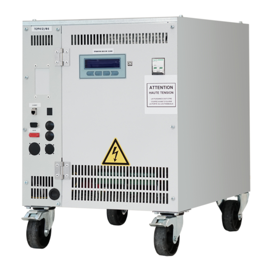
DIAM3200 FIXTURE DESCRIPTION General characteristics The DIAM3200 constant current regulators are designed for the purpose of powering series circuits for luminous fixtures of airport areas: runways, taxiways and aircraft aprons. The DIAM3200 constant current regulators (URCC) are optimized static power supplies, whose control is ensured by insulated gate bipolar transistors (IGBT), capable of maintaining constant the output steps independently from the load fluctuations and the supply voltage. The DIAM3200 constant current regulators are stackable (max. 3 units) to optimize the space they occupy on the ground. The DIAM3200 constant current regulators are compliant with the rules: IEC 61822, Edition 2.0 AENA DIN/DNYM/PPT/002-05/13 The DIAM3200 constant current regulators described in this manual have been designed to be installed on the levelled floor with adequate flatness and strength characteristics. The normal installation condition is a fixed, stable and non-slip floor, free of protuberances, hollows or inclined planes, designed and constructed with characteristics suitable to the actual operating conditions. -
Page 12: Operating Principle
DIAM3200 Operating principle The control and management system of the device is scheduled to manage the operation of the constant current regulator automatically. The unit also provides the possibility of advanced functions, which can be activated by the user if required (Wig-Wag mode and 4-20 mA mode). When a brightness level is selected, the system activates the main contactor and adjusts the bipolar transistors to supply the output series circuit with a current value in accordance with the set value. The device continuously measures the loop current (via a Hall effect sensor), which is compared with the set value. The detected rejection is used to correct the operating parameters via a digital regulator. The dischargers on the output line of the device (OLA) protect the device from any overvoltages in the circuit. The burnt lamps detector (LFD) allows the detection of the presence of burnt lamps on the series circuit. If used, the LFD function must be properly configured and calibrated on the field. Optional devices perform control and monitoring of the operating parameters, disconnection manoeuvres of the output circuit to the load, and input overvoltage protection, simplifying the operation and functioning of the device: ● An insulation monitoring system (EFD) allows continuous analysis of the resistance value between the series circuit and earth, signalling the exceeding of the pre-alarm and alarm thresholds. ● An output disconnection device (CUT-OUT) simplifies the maintenance on the HV side: units equipped with the disconnection device can be serviced without the need to disconnect the series circuit terminals and the earth connection. ● Input discharger (ILA) system to protect against overvoltages on the unit's supply line of the device. In addition to local control, the constant current regulator can also be controlled remotely through suitable connection interfaces. Supervision of the constant current regulator management system can be done through the integrated display and keypad, or through the Alize software interface (using an external PC connected via USB cable to the controller). By means of the optional integrated output circuit selector (ICS), it is possible to select which portion of the series circuit to power, in addition to the set current level. UT-MT-0938_1.0_30-03-2023 (EN) Use and Maintenance Manual... -
Page 13: Reference Standards
DIAM3200 Reference standards The constant current regulators are manufactured in accordance with the following standard: ● IEC 61822, Edition 2.0: Electrical installations for lighting and signalling in airports and heliports - Constant current regulator. ● AENA DIN/DNYM/PPT/002-05/13: Technical specifications for constant intensity controllers. Nb. of steps The constant current regulators can be equipped with a number of steps varying from 1 to 8, each configurable in the range 1.8-6.6 A, to meet different end-user requirements. According to IEC 61822, the nominal output current range is: ● Type 1: from 4.8 to 6.6 A ● Type 2: from 2.8 to 6.6 A The table provides the normalised CCR pre-settings. These settings can be modified in accordance with the requirements of an airport. Type Nb. of steps 6.6 A 5.5 A 4.8 A... -
Page 14: Supply Voltage
DIAM3200 Supply voltage The constant current regulators can be supplied with different voltage levels, depending on the network values. The single-phase power supply can be chosen from the following values: 220, 230, 240V [±10 % (IEC), 50/60 Hz]. The two-phase power supply can be chosen from the following values: 380, 400 o 415V [±10 % (IEC), 50/60 Hz]. Attention: The supply voltage value chosen when ordering cannot be changed. Nominal power The constant current regulators provide a maximum output voltage that can be selected according to requirements: ● 2,5 kVA ● 5,0 kVA ● 6,5 kVA Attention: The nominal power value chosen when ordering cannot be changed. Wired remote control The constant current regulators can be configured to be controlled and monitored through dry contacts (relay 125 V /2 A or 125 V /2 A for resistive loads) and by an internal or external voltage (from 20 to 60 V , positive or negative) or through wired connector (32 PIN). -
Page 15: Product Code
DIAM3200 2.11 Product Code example: D32 - IEC 5 - 40 02 - F 6 6 A - ICS2 - S2 - Reference standards IEC = IEC (61822, Edition 2.0) ( ) = AENA (DIN/DNYM/PPT/002-05/13) ( ) Nb. of steps (brightness - from 1,8 to 6,6 A): from 1 =1 nb. of steps = 8 nb. of steps Supply voltage: = 220 V... -
Page 16: Behaviour In Case Of Fault
DIAM3200 2.12 Behaviour in case of fault If the unit detects a fault or an error, the control system applies corrections and informs the operator through a message on the display. The possible types of warning are: ● WARNING: the constant current regulator continues normal operation but alerts the operator that a problem is present (this is the case with EFD or LFD fault). ● ALARM: the constant current regulator is unable to continue normal operation and interrupts the current supply due to an internal fault (e.g. alarm of one of the overcurrent threshold levels) or an external fault (e.g. open circuit). When a fault occurs, prompt action must be taken to identify the cause of the fault and eliminate the problem. The system can only be reset by means of a manual reset (STOP key). The unit preserves the memory of messages detected during operation even in the event of the supply voltage. -
Page 17: Wiring
DIAM3200 2.13 Wiring To wire the DIAM3200 system properly, use only cables compliant with the relevant technical specifications (FAA L-824, IEC/EN 60228), specially designed for airport installations and safety-critical systems. The cables necessary for the functioning of the unit are not included in the supply. It is the customer’s responsibility to arrange appropriate certified equipment to connect the units. Before connecting the unit, check that the unit configuration is compatible with the actual system conditions. - Page 18 DIAM3200 Page intentionally left blank UT-MT-0938_1.0_30-03-2023 (EN) Use and Maintenance Manual...
-
Page 19: Installation
DIAM3200 INSTALLATION Constant current regulator The DIAM3200 constant current regulators, installed to supply the series circuits, are capable of supplying current to the series circuit to provide the necessary brightness to the light fixtures installed on the circuit. The number of selectable brightness levels must be consistent with the intended functionality of the circuit design. The features of series circuit must be compliant with the dispositions of competent bodies and with the regulations in force. The load actually supplied by the series circuit must not exceed the operating limits of the constant current regulator. For the construction of the supply circuits and for the series circuits, refer to the requirements of the relevant Standards. For the conformity of the light fixtures supplied by the constant current regulators through the series circuits, refer to the specific product certifications. -
Page 20: Handling And Positioning Of The Device
DIAM3200 Handling and positioning of the device To position the device correctly, take the following aspects into consideration: ● Access to the unit from the front side must be guaranteed to make operation and maintenance procedures easy. ● The constant current regulators can be arranged side by side or stacked one on top of the other (up to a maximum of 3) to optimise floor space. Attention: stacking is the responsibility of the Manufacturer and must be requested in the article code when ordering. ● Maintain a free space of at least 20 cm at the rear side of the unit to ensure proper ventilation of the device. Before proceeding with the operation, check the conditions of the device: ● check that the mechanical fixing of the components are steady; ● check that the internal connections are properly tightened; ● check that the internal equipotential connections are all well realized. Always use lifting equipment of suitable characteristics: before handling the load, check the weight and dimensions of the load to be lifted, verifying the correct positioning of the centre of gravity. -
Page 21: Preliminary Checks
DIAM3200 Preliminary checks Store the device in its original packaging until the time of installation. Check the characteristics of the electrical system into which the device must be integrated before installing the constant current regulator. ● The power supply line must be suitably dimensioned and adequately protected. ● Only use the device in combination with series circuits that comply with the standard FAA AC 150/5340-30 and ICAO Aerodome Design Manual Part 5. ●... -
Page 22: Connection To The Power Supply
DIAM3200 Connection to the power supply Before carrying out any intervention on the device, cut off all external power sources and place appropriate work-in-progress warnings on the systems. Wait for the discharging time (at least 5 min) and check using appropriate instruments that there are no residual energies before accessing the electrical equipment. -
Page 23: Connection Of The Series Circuit
DIAM3200 Connection of the series circuit Before carrying out any intervention on the device, cut off all external power sources and place appropriate work-in-progress warnings on the systems. Wait for the discharging time (at least 5 min) and check using appropriate instruments that there are no residual energies before accessing the electrical equipment. -
Page 24: Remote Control Configuration
DIAM3200 Remote control configuration The connection for remote control varies depending on the configuration of the device. The connections are available on the back of the unit. Connect the prepared cables to the respective doors of the device. The units can be equipped with 1 or 2 serial communication interfaces. The basic configuration includes one RS485 type serial port. UT-MT-0938_1.0_30-03-2023 (EN) Use and Maintenance Manual... -
Page 25: External Circuit Selector Interlock
DIAM3200 External circuit selector interlock The unit is supplied already wired to operate without an external circuit selector. To operate, the two terminals S1 and S2 are short-circuited (removable jumper). To operate in combination with an external selector, it is necessary for the unit to stop the supply at least 100 ms before the circuit changeover occurs in order to prevent transitory overcurrents from drastically reducing the life of the powered lamps. -
Page 26: Tests And Checks
DIAM3200 Tests and checks At the end of the installation (before commissioning) and whenever necessary, carry out function tests and checks. Always follow the safety instructions in order not to create dangerous situations for persons or property. 3.8.1 Short-circuit test Do not perform this test if there is any doubt about the correct operation of the unit, or if there is a fault or breakage. - Page 27 DIAM3200 3.8.2 Open circuit test Do not perform this test if there is any doubt about the correct operation of the unit, or if there is a fault or breakage. ● Act on the main switch and switch off the unit. ● De-energise the power supply and wait for the discharging time. ● Open the rear cover and completely disconnect the series circuit. If the unit is equipped with a SIMALT2 device, it is possible to disconnect the series circuit without acting on the wirings, by removing the jumpers CCR (for more information, see document ES-MT-0113 accompanying the CUT-OUT device).
- Page 28 DIAM3200 Page intentionally left blank UT-MT-0938_1.0_30-03-2023 (EN) Use and Maintenance Manual...
-
Page 29: Adjustments And Maintenance
DIAM3200 ADJUSTMENTS AND MAINTENANCE After completing the installation, check that all the fixed guards are closed. Only now is possible to close the upstream cut-out to supply the device. Preliminary operations Act on the local cut-out (thermal-magnetic circuit breaker CB - standard), by rotating it in ON position. When the device is ONLINE (constant current regulator powered) the display switches on, the system is initialized and the device will revert to STOP mode: the controller’s control system is active, but the series circuit is disconnected. During operation, the display always shows the output current (1) and a second parameter (2) selectable as desired by the user: <Bx>... -
Page 30: Selection Of The Operation Mode
DIAM3200 Selection of the operation mode The unit is supplied with a pre-set of parameters in accordance with the machine configuration. For normal use, reconfiguration is not necessary during installation operations. Starting from the STOP mode the constant current regulator can power the series circuit operating in different modes: ● LOCAL mode (1): press the LOCAL button (P2) to select the local control mode. The display shows the current level delivered and the operator can manually select a different level by pressing the B- (P2.2) and B+ (P2.3) buttons depending on the needs. ● REMOTE CONTROL mode: press the AUTO button (P3) to select the remote control mode. The display shows the current operating parameters (the Io output current and a second user-selected parameter). The controller ●... -
Page 31: Navigation Map
DIAM3200 Navigation map During operation, the display always shows the output current and a second parameter selectable as desired by the user: <Bx> level of brightness, output power Po (in kVA), output voltage Uo (in V). UT-MT-0938_1.0_30-03-2023 (EN) Use and Maintenance Manual... -
Page 32: Local Monitoring
DIAM3200 Local monitoring Through the monitoring menu, it is possible to read the real-time values of the main quantities measured by the system: ● Uo: output voltage (expressed in Vrms) ● Po: output power (expressed in kVA) ● Ui: input voltage (expressed in Vrms) ● Earth Fault: insulation resistance value (expressed in kΩ) ● Burnt lamps: number of burnt lamps on the circuit (if the option LFD is activated) ● Operating time: operating time (expressed in hours) both overall and for each expected brightness level. UT-MT-0938_1.0_30-03-2023 (EN) Use and Maintenance Manual... -
Page 33: Warning, Fault And Alarm Messages
DIAM3200 Warning, fault and alarm messages Next to the type of problem there is a short message explaining the fault detected. In the case of WARNING, the possible messages are: ● LFD level 1: with the LFD (Lamp Fault Detector) option enabled, it signals the presence of a number of burnt lamps higher than the value set for the threshold level 1. ● LFD level 2: with the LFD (Lamp Fault Detector) option enabled, it signals the presence of a number of burnt lamps higher than the value set for the threshold level 2. ● Meas. lamps: the measuring sensor is unable to provide the required values. ● EFD level 1: with the EFD (Earth Fault Detector) option enabled, it signals an excessive earth resistance value compared to the value set for the threshold level 1. ● EFD level 2: with the EFD (Earth Fault Detector) option enabled, it signals an excessive earth resistance value compared to the value set for the threshold level 2. ● No EFD: the measuring electronic board is unable to provide the required values. ● BAD Freq.: the supply line frequency is outside the permissible range or an asymmetrical wave shape is detected. ● TC-TS board: the wired remote control is faulty/not present. ● Regulation error: the measured values exceed the limits (I ) defined for each available setting BnMIN BnMAX (B0...B7). -
Page 34: Troubleshooting
DIAM3200 Troubleshooting Before proceeding to delete the message, identify the cause of the fault and eliminate the problem. Check the general status of the device. If necessary, consult the manual to identify the problem and the possible causes of failure. Eliminate the problem and press the RESET button (P1) to restore the system. A system reset is only possible with the system energised in STOP mode. The unit preserves the memory of messages detected during operation even in the event of the supply voltage. -
Page 35: Access To The Parameters
DIAM3200 Access to the parameters To prevent unintentional modification of operating values, the system only allows access to parameters after the relevant function has been enabled. Enabling the change function and updating the values is only possible with the system energised in STOP mode. -
Page 36: Edit Parameters
DIAM3200 Edit parameters The unit is supplied with a pre-set of parameters in accordance with the machine configuration. For normal use, reconfiguration is not necessary during installation operations. Parameter change is only possible with the system energised in STOP mode and with the parameter access option enabled. - Page 37 DIAM3200 4.8.1 Parameter diagram and suggested configuration values The unit is supplied with a pre-set of parameters in accordance with the machine configuration. The parameter diagram with suggested configuration values is presented below. Please check the actual configuration of the device. Some parameters may not be available, if the relevant option is not present on the device. UT-MT-0938_1.0_30-03-2023 (EN) Use and Maintenance Manual...
- Page 38 DIAM3200 Please check the actual configuration of the device. Some parameters may not be available, if the relevant option is not present on the device. UT-MT-0938_1.0_30-03-2023 (EN) Use and Maintenance Manual...
- Page 39 DIAM3200 Please check the actual configuration of the device. Some parameters may not be available, if the relevant option is not present on the device. UT-MT-0938_1.0_30-03-2023 (EN) Use and Maintenance Manual...
- Page 40 DIAM3200 Please check the actual configuration of the device. Some parameters may not be available, if the relevant option is not present on the device. UT-MT-0938_1.0_30-03-2023 (EN) Use and Maintenance Manual...
-
Page 41: Software Configuration Utility
DIAM3200 Software configuration utility In order to make the functionality of the device more usable, it is possible to connect to the constant current regulator control system using the USB connection (located on the front of the device) with a PC with the ALIZE 4100 software installed. The ALIZE 4100 software (available for download from the link on the manufacturer's website: http://www.augier.com/soft/ALIZE4100.exe). -
Page 42: Scheduled Maintenance
DIAM3200 4.10 Scheduled maintenance The CAN architecture of the DIAM3200 CCR controller of the OCEM Airfield Technology is designed to minimise the number and variety of spare parts and to allow wide configurability of the options. OCEM Airfield Technology offers software tools to perform quick parameter settings or diagnostics, without having to remove any parts. Before carrying out any intervention on the device, cut off all external power sources and place appropriate work-in-progress warnings on the systems. Wait for the discharging time (at least 5 min) and check using appropriate instruments that there are no residual energies before accessing the electrical equipment. -
Page 43: Corrective Maintenance - Component Identification
DIAM3200 4.11 Corrective Maintenance - Component Identification Before carrying out any intervention on the device, cut off all external power sources and place appropriate work-in-progress warnings on the systems. Wait for the discharging time (at least 5 min) and check using appropriate instruments that there are no residual energies before accessing the electrical equipment. - Page 44 DIAM3200 ● Parts accessible from the front side mother board (and relevant protective fuses FU1 and FU2) interface board measurement board EFD board main thermal-magnetic circuit breaker CB (Q1) EMC filter power contactor (KM) power module complete with fans power supply autotransformer wired remote control board/IEC/AENA (optional, for more information, see document ES-MT-0112) cut-out SIMALT disconnector (optional, for more information, see document ES-MT-0113) The device could be equipped with ICS integrated circuit selector (optional, for more information, see document ES-DP-0007). UT-MT-0938_1.0_30-03-2023 (EN) Use and Maintenance Manual...
-
Page 45: Troubleshooting
4.12.1 Fault of the supply line Problems Possible causes Possible solution The constant current regulator inhibited the supply (STOP mode). The display shows one of the following messages: ● ALARM: BAD SUPPLY A fault of the supply line has occurred. 1. Check the supply voltage value. 2. Check the POWER SUPPLY CCR parameter setting in the CONFIGURATION menu. If necessary, use the ALIZE 4100 software. 3. Check the VOLTAGE MEASUREMENT parameter setting in the SUPERVISION menu. If necessary, use the ALIZE 4100 software. If after trying the proposed solutions the problem persists, contact OCEM Customer Service. UT-MT-0938_1.0_30-03-2023 (EN) Use and Maintenance Manual... - Page 46 The parameters set for Open Circuit 1. Check the OPEN CIRCUIT parameter setting in the ALARM (intervention threshold and inhibition AND WARNINGS menu. If necessary, use the ALIZE 4100 time) cause the supply to stop. software. If after trying the proposed solutions the problem persists, contact OCEM Customer Service. 4.12.3 Over current Problems: over current Possible causes Possible solution The constant current regulator inhibited the supply (STOP mode). The display shows one of the following messages: ● ALARM: I>>Level 1 ●...
- Page 47 1. Check the status of the power board. If necessary, use the DIAGNOSTIC function of the ALIZE 4100 software. If necessary, replace the board. 2. If, after replacing the fuses, the fuses burn out again during testing, proceed to replace the board. If after trying the proposed solutions the problem persists, contact OCEM Customer Service. UT-MT-0938_1.0_30-03-2023 (EN) Use and Maintenance Manual...
- Page 48 WARNING: LFD level 1 ● WARNING: LFD level 2 The current values on the series circuit 1. Check the status of the fixture installed on the series circuit. may be unstable and the expected If necessary, replace the burnt lamps. fixture brightness values may not be 2. Check the LAMP FAULT DETECTION parameter setting in met. the WARNING AND ALARMS 2 menu. If necessary, use the ALIZE 4100 software. 3. Run the learning function again. If after trying the proposed solutions the problem persists, contact OCEM Customer Service. UT-MT-0938_1.0_30-03-2023 (EN) Use and Maintenance Manual...
- Page 49 The display shows one of the following messages: ● WARNING: TC-TS board Wired remote control is not detected. 1. Check the status of the remote control relay board. If necessary, replace the board. If after trying the proposed solutions the problem persists, contact OCEM Customer Service. UT-MT-0938_1.0_30-03-2023 (EN) Use and Maintenance Manual...
- Page 50 The display shows one of the following messages: ● WARNING: Temp. Sensor The temperature probe installed on the 1. Check the status of the probe connections. If necessary, heatsink may be faulty. replace the probe (R = 10kΩ). 25°C If after trying the proposed solutions the problem persists, contact OCEM Customer Service. UT-MT-0938_1.0_30-03-2023 (EN) Use and Maintenance Manual...
- Page 51 DIAM3200 Identifying mother board components Identifying measurement board components UT-MT-0938_1.0_30-03-2023 (EN) Use and Maintenance Manual...
-
Page 52: Spare Parts
DIAM3200 4.13 Spare parts Always check the version of the device you have and any options/accessories present. Constant current regulator DIAM3200 Front segregation Rear segregation Accessories Code Art. Fixed wheels Swivel castors Lifting rings (single unit) Lifting bars (2 overlapping units) Lifting bars (3 overlapping units) UT-MT-0938_1.0_30-03-2023 (EN) Use and Maintenance Manual... - Page 53 DIAM3200 4.13.1 Front segregation Description Product Code Code Art. IEC/AEN - 22/23/24 02 - 10.25251 █ █ IEC/AEN - 38/40/41 02 - 10.25250 █ █ IEC/AEN - 22/23/24 05 - 10.25254 █ █ Magnetothermal input protection (DJ1) IEC/AEN - 38/40/41 05 - 10.25251 █...
- Page 54 DIAM3200 Description Product Code Code Art. IEC/AEN - 22/23/24 718.3110 █ █ █ █ Power module IEC/AEN - 38/40/41 718.3111 █ █ █ █ UT-MT-0938_1.0_30-03-2023 (EN) Use and Maintenance Manual...
- Page 55 DIAM3200 Description Product Code Code Art. Fuses mother board always valid 30.12819 Mother board protective fuses (FU1/FU2) always valid 10.27584 Membrane keyboard always valid 10.20483 Display always valid 30.12449 EFD board always valid 30.10029 Measurement board always valid 30.08004 Interface board always valid 30.10028 Wired remote control board (dry contacts) IEC/AENA always valid 30.13547 A - ICS █...
- Page 56 DIAM3200 4.13.2 Rear segregation Description Product Code Code Art. EFD board - H.V. always valid 30.11451 IEC/AEN - 22/23/24 02 - 10.24847 █ █ IEC/AEN - 38/40/41 02 - 10.26711 █ █ IEC/AEN - 22/23/24 05 - 10.26712 █ █ Power transformer (T1) IEC/AEN - 38/40/41 05 - 10.26713...
- Page 57 Contact us OCEM AT +39 051 66 56 611 info@ocem.com...
- Page 58 Stackable Constant Current Regulator (IGBT) OCEM AT a division of ENERGY TECHNOLOGY S.r.l. Via della Solidarietà, 2/1 - 40056 Valsamoggia (Bologna) - Italy ocem...
Need help?
Do you have a question about the DIAM3200 IGBT and is the answer not in the manual?
Questions and answers